Thermal container

a container and thermal insulation technology, applied in the field of containers, can solve problems such as unwanted heat loss, and achieve the effect of eliminating heat loss through the open passag

Inactive Publication Date: 2005-11-29
CONAIR CORP
View PDF27 Cites 12 Cited by
  • Summary
  • Abstract
  • Description
  • Claims
  • Application Information

AI Technical Summary

Benefits of technology

[0011]It is still a further object of the present invention to provide a container that substantially eliminates heat loss by allowing the filling and dispensing of the container through filling and dispensing channels that are thermally sealed when not in use.

Problems solved by technology

However, the open passage also allows unwanted heat loss, typically by steam passing back through the open passage.

Method used


Image

  • Thermal container
  • Thermal container
  • Thermal container

Examples


Embodiment Construction

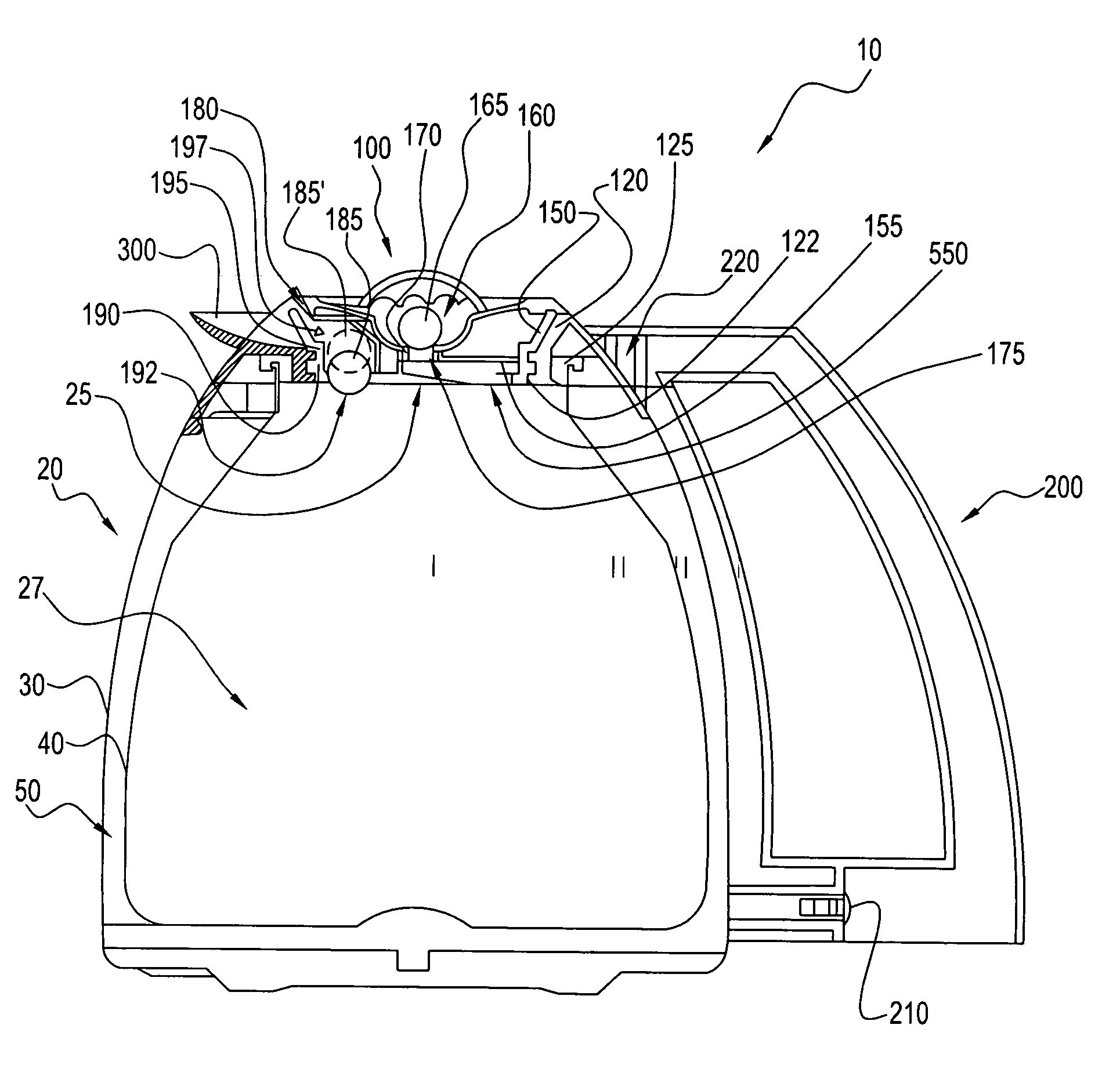
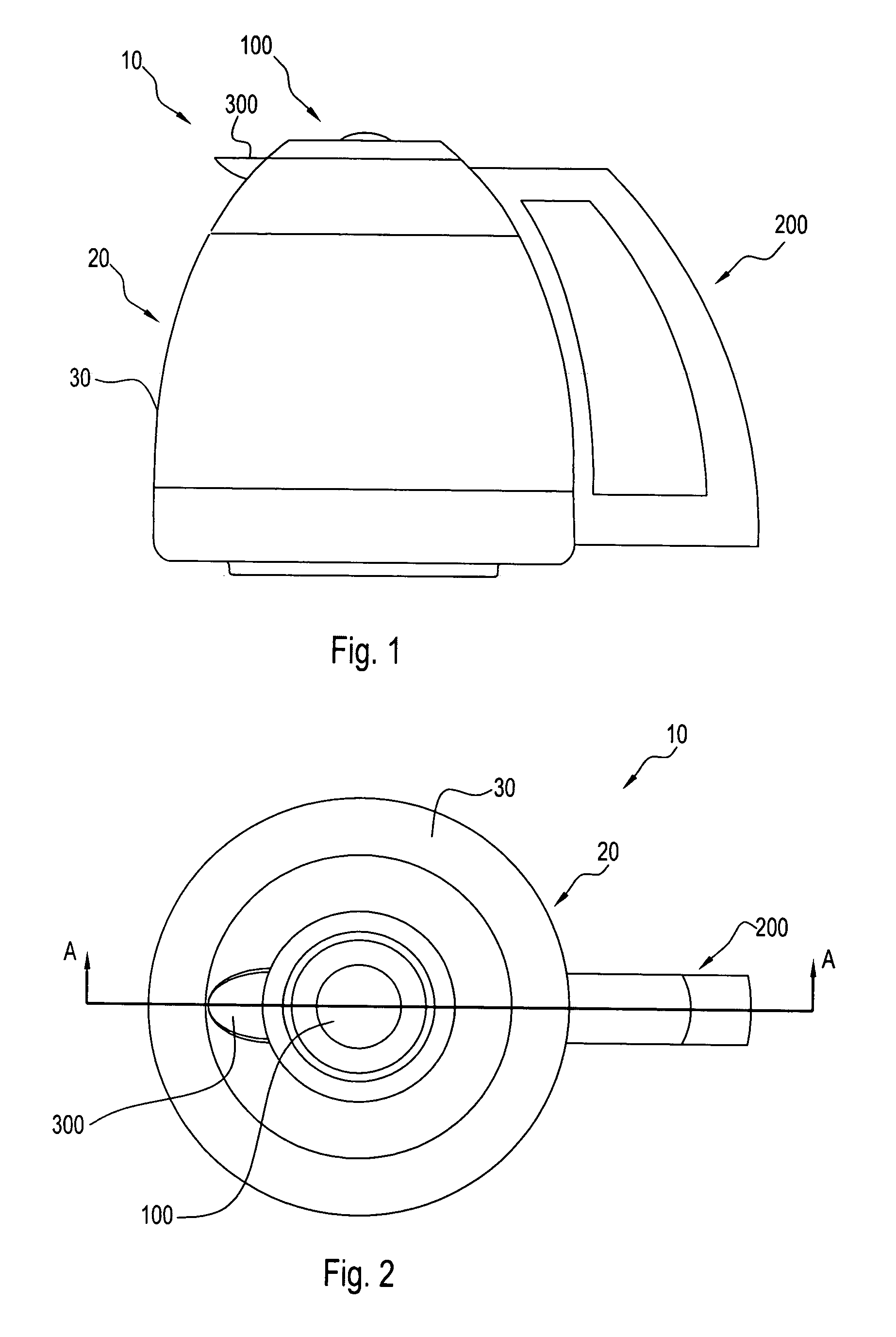
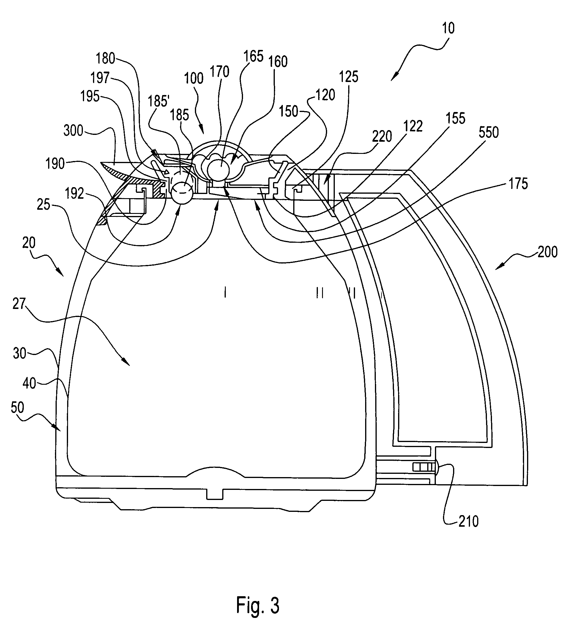
[0026]Referring to the figures and, in particular, to FIGS. 1 and 2, there is provided a container generally represented by reference numeral 10. Container 10 has a body 20, a lid 100 that can be removably secured to the body, and a handle 200 that is preferably secured to the body.

[0027]Referring to FIGS. 1 and 3, body 20 is preferably substantially cylindrical in shape. Body 20 has an opening 25 through which a substance may enter and exit container 10. Preferably, body 20 has a hollow area or inner volume 27 of about 1.5 liters. However, the inner volume 27 can have a smaller or larger capacity. Opening 25 is preferably circular but can be other shapes depending upon the shape of body 20. Body 20 has an outer wall 30 and an inner wall 40. Outer wall 30 and inner wall 40 are separated to define therebetween a thermal space 50. Preferably, thermal space 50 provides a vacuum between outer and inner walls 30, 40 for improved thermal insulation of container 10. Outer and inner walls 3...


PUM


Abstract

A container is provided. The container has a cover that remains thermally, sealingly engaged with the container during the filling and dispensing of the container, and has filling and dispensing channels that are thermally sealed when not in use.

Description

RELATED APPLICATIONS[0001]This application is related to, and claims priority in, co-pending U.S. Provisional Application Ser. No. 60 / 347,309, filed Jan. 10, 2002 and co-pending U.S. Provisional Application Ser. No. 60 / 367,137, filed Mar. 22, 2002, the disclosures of which are incorporated herein by reference.BACKGROUND OF THE INVENTION[0002]1. Field of the Invention[0003]The present invention relates to one or more containers. More particularly, the present invention relates to one or more thermally insulated containers.[0004]2. Description of the Prior Art[0005]Automatic drip brewing devices are known in the art. These devices require an open passage that allows the brewed beverage to flow from the brewing device to the container and an open passage for dispensing the brewed beverage from the container. However, the open passage also allows unwanted heat loss, typically by steam passing back through the open passage.[0006]The present invention relates to an improved container that...

Claims


Application Information

Patent Timeline
Patent Type & Authority Patents(United States)
IPC IPC(8): A47J41/00A47J41/02
CPCA47J41/0027A47J41/028
Inventor MULLE, THEODORE B.
Owner CONAIR CORP
Why Eureka
Try Eureka