Scarf nozzle for a jet engine and method of using the same

Active Publication Date: 2005-11-29
THE BOEING CO
View PDF11 Cites 45 Cited by
  • Summary
  • Abstract
  • Description
  • Claims
  • Application Information

AI Technical Summary

Benefits of technology

[0004]Accordingly, a need exists in the art for a device and method that mitigates the adverse effect that a nacelle nozzl

Problems solved by technology

The relative location of a nacelle nozzle to a wing can adversely affect the wing's pressure gradients and thus the drag of the wing as a result of the interaction of exhaust gases and ambient air adjacent the nozzle.
For example, locating a nozzle relatively close to the most adverse pressure gradient on a wing can easily lead to an increase in the wing's adverse pressure gradient to the point at which the drag of the wing is not desirable.
In addition, the close proximity of an engine nacelle to the wing undersurface can also lead to the formation of ear

Method used


Image

  • Scarf nozzle for a jet engine and method of using the same
  • Scarf nozzle for a jet engine and method of using the same
  • Scarf nozzle for a jet engine and method of using the same

Examples


Embodiment Construction

[0018]The following description of the preferred embodiment(s) is merely exemplary in nature and is in no way intended to limit the invention, its application, or uses.

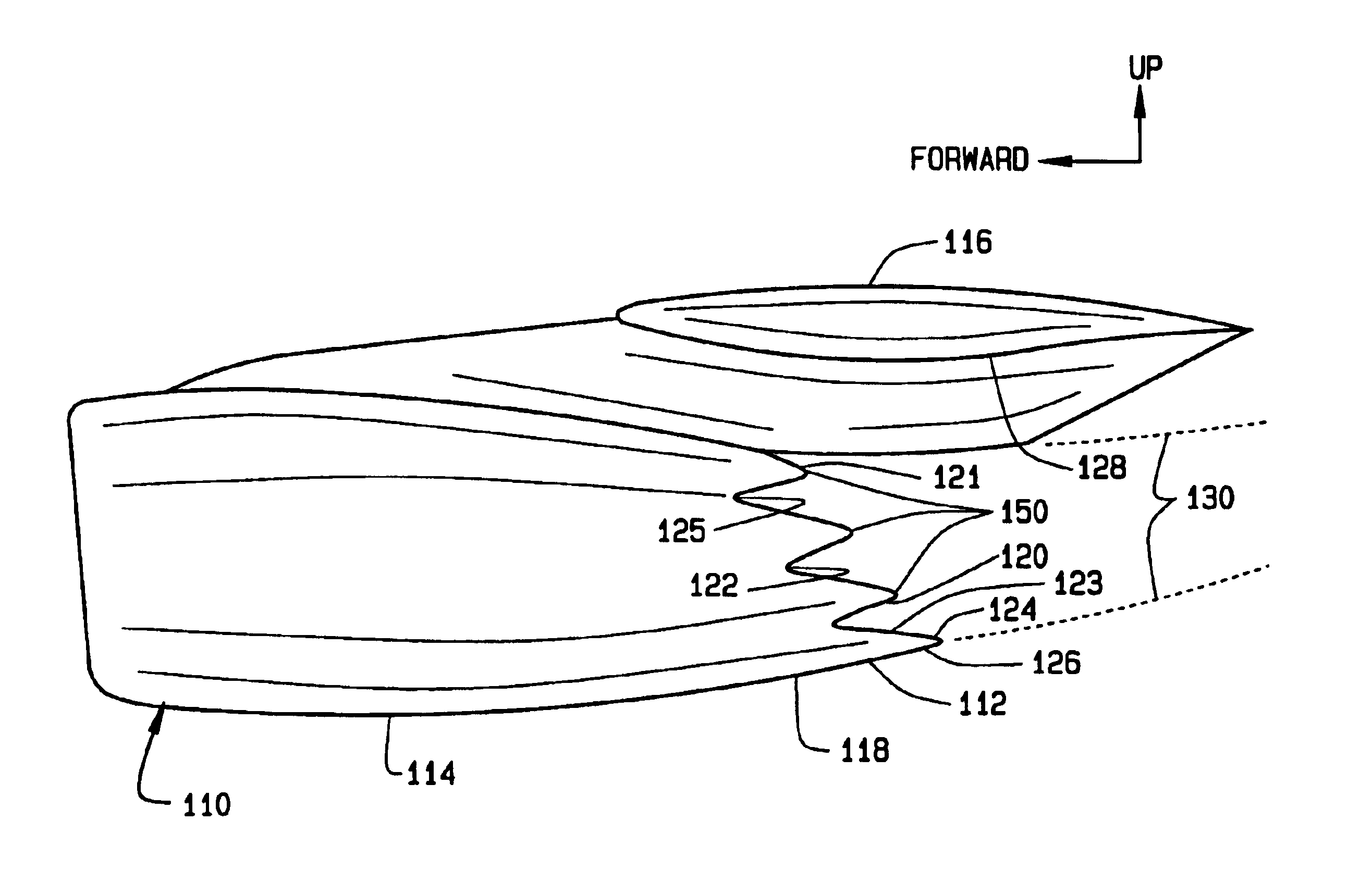
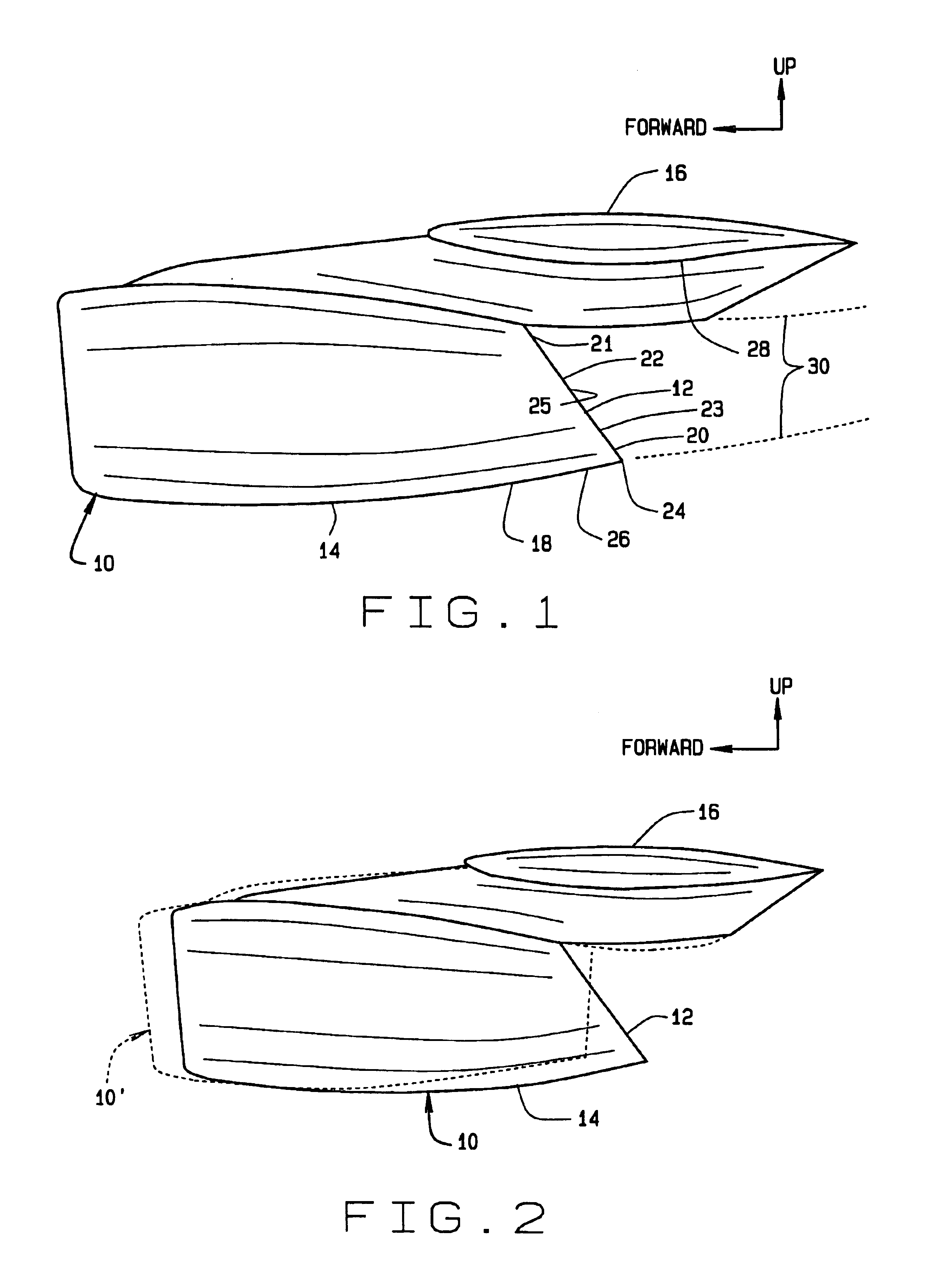
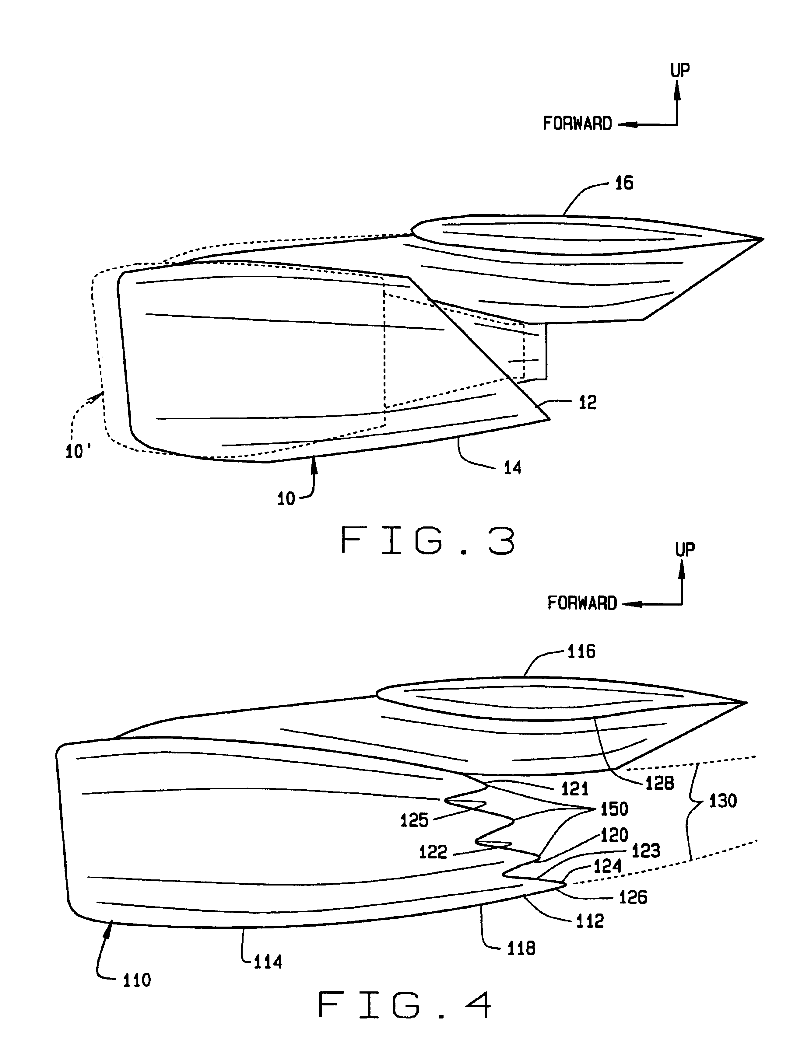
[0019]Referring to FIG. 1, there is shown an exemplary jet engine 10 of a mobile platform, such as an aircraft, that includes a scarf nozzle 12 in accordance with a preferred embodiment of the present invention. The jet engine 10 includes a housing or nacelle 14 that is shown mounted under an aircraft wing 16, although such is not required. It should be noted that the nacelle 14 need not comprise a long-duct nacelle as shown in FIGS. 1 and 2, but may, for example, comprise a ¾-duct nacelle as shown in FIG. 3.

[0020]The scarf nozzle 12 is formed at an aft end 18 of the nacelle 14. As explained in greater detail below, the scarf nozzle 12 is configured to allow at least a portion of an exhaust plume 30 exiting the aft end 18 of the nacelle 14 to interact more favorably with an airflow along one or more surfaces adjacent ...


PUM


Abstract

A scarf nozzle for a jet engine supported within a nacelle. The scarf nozzle is at an aft end of the nacelle. The scarf nozzle includes a first trailing edge portion and a second trailing edge portion. The second trailing edge portion is disposed aft of the first trailing edge portion. The scarf nozzle is configured to allow the nacelle to be integrated closer to a wing without adversely affecting the pressure gradient between the nacelle and the wing. The scarf nozzle allows a portion of an exhaust plume exiting the aft end of the nacelle to interact more favorably with an airflow along one or more surfaces adjacent the nacelle, thus delaying the onset of adverse pressure gradients and the formation of shock waves between the nacelle and the adjacent surfaces and between the adjacent surfaces and the exhaust plume.

Description

FIELD OF THE INVENTION[0001]The present invention relates generally to jet engines and more particularly to jet engine nacelle nozzles.BACKGROUND OF THE INVENTION[0002]The relative location of a nacelle nozzle to a wing can adversely affect the wing's pressure gradients and thus the drag of the wing as a result of the interaction of exhaust gases and ambient air adjacent the nozzle. For example, locating a nozzle relatively close to the most adverse pressure gradient on a wing can easily lead to an increase in the wing's adverse pressure gradient to the point at which the drag of the wing is not desirable. In addition, the close proximity of an engine nacelle to the wing undersurface can also lead to the formation of early shock waves generated from the high flow velocities between the wing undersurface and the nacelle and / or between the wind undersurface and the exhaust plume.[0003]To mitigate a nacelle's influence on a wing's pressure field, a common method includes positioning na...

Claims


Application Information

Patent Timeline
IPC IPC(8): B64D33/04F02K1/44F02K1/52
CPCB64C7/02B64D33/04F02K1/52F02K1/44Y02T50/671Y02T50/60
Inventor DUN, ROY
Owner THE BOEING CO
Why Eureka
Try Eureka