Blowout preventer and ram actuator

a technology of ram actuator and blowout rod, which is applied in the direction of sealing/packing, earthwork drilling and mining, and wellbore/well accessories, etc., can solve the problems of lock rod and expensive repairs

Active Publication Date: 2005-11-29
VARCO I P INC
View PDF79 Cites 68 Cited by
  • Summary
  • Abstract
  • Description
  • Claims
  • Application Information

AI Technical Summary

Benefits of technology

[0009]The present invention, in certain aspects, teaches a ram-type blowout preventer with rams actuated by dual-piston actuators. A dual piston actuator according to the present invention, has, in certain aspects, housings in which a primary piston and a booster piston are simultaneously movable to move a ram shaft which in turn moves a ram of the blowout preventer. In one particular aspect the pistons are located, sized, and configured so that, upon movement and closure of the rams, the force of the booster piston on the rams is eliminated by limiting the booster piston's travel when the primary piston is near full stroke travel. To maintain the rams in a closed position while the force of the booster position on the rams has been eliminated, a movable locking member within and extending through a bore of the booster piston is selectively movable to abut an end of the ram shaft to mechanically maintain the ram shaft and its associated ram in a ram-closed position.
[0014]Such blowout preventers with ram actuators having dual pistons and apparatus for selectively eliminating the force of one of the pistons on a ram shaft whose movement effects ram closure;
[0016]Such blowout preventers with such actuators which eliminate the force of a booster piston on rams so that pressure on ram seals and / or parts of ram blocks and / or ram block faces is reduced and / or damage to a lock rod is inhibited; and
[0017]New, useful, unique, efficient, and nonobvious blowout preventers which provide sufficient force to close rams therein, shearing a tubular around which the blowout preventer, yet which, compared to certain previous apparatuses, are relatively smaller and weigh relatively less.

Problems solved by technology

If, upon such inadvertent opening, the force of both pistons was applied to the lockrod, the lock rod could bend preventing unlocking of the blowout preventer and opening of the rams and requiring expensive repairs.

Method used


Image

  • Blowout preventer and ram actuator
  • Blowout preventer and ram actuator
  • Blowout preventer and ram actuator

Examples


Embodiment Construction

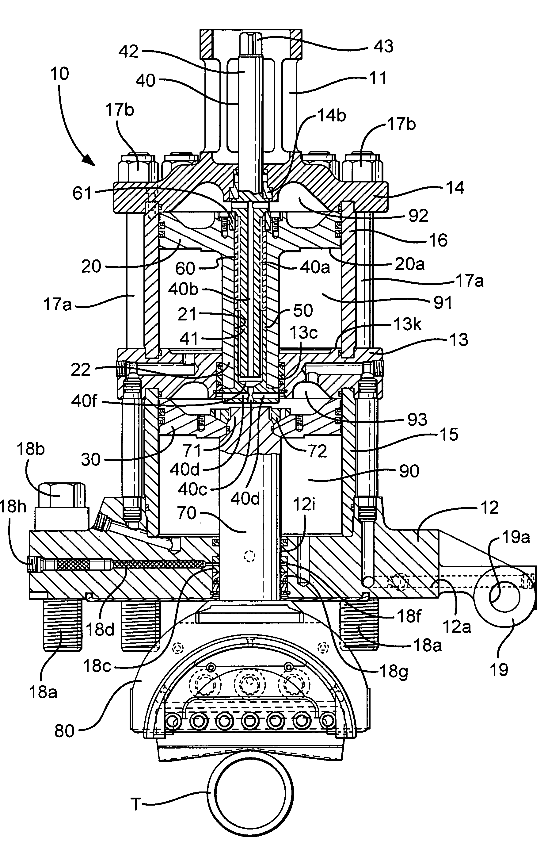
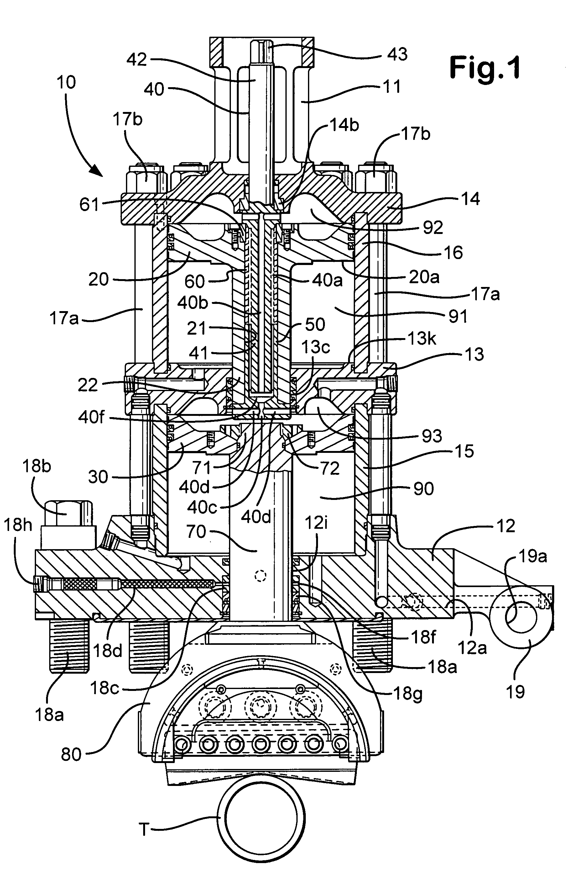
[0024]FIG. 1 shows an actuator 10 for a ram 80 of a ram-type blowout preventer (e.g. a blowout preventer as shown in FIG. 3) used with a tubular T. A base (or door) 12 is connected to a blowout preventer body with bolts 18a and nuts 18b. Optionally, the base 12 (and hence the actuator 10) is pivotally mounted to the blowout preventer using a pivot assembly 19 movably secured with a pin (not shown) through a hole 19a. A primary housing 15 with a generally cylindrical hollow shape supports a middle plate 13 that closes off the top of the primary housing 15. A secondary housing 16 with a generally cylindrical hollow shape supports a cylinder head 14 that closes off the top of the upper housing 16.

[0025]A primary piston 30 is movably situated in the primary housing 15. An end 71 of a ram shaft 70 is secured to the primary piston 30 with a lock nut 72. Movement of the primary piston 30 moves the ram shaft 70 and a ram 80 connected thereto. The ram shaft 70 moves in a bore 12i of the base...


PUM


Abstract

A blowout preventer with a main body; a base releasably connected to the main body, the base having a base space therein, the base having a ram shaft opening; a primary piston movably disposed within the base space; a ram shaft to which the primary piston is connected, the ram shaft including a ram end and a piston end; a ram connected to the ram end of the ram shaft; a housing connected to the base, the housing having a housing space therein, the housing including a middle member with a member opening; a booster piston movably disposed within the housing space and having a booster shaft projecting therefrom and a booster shaft space therein; the shaft including a push portion selectively movable to abut the ram shaft to prevent movement of the ram shaft and to transfer force of the booster piston to the primary piston; and power fluid apparatus for the primary piston and the booster piston.

Description

BACKGROUND OF THE INVENTION[0001]1. Field of the Invention[0002]The present invention is directed to blowout preventers, to actuators for blowout preventer rams, and to methods of their use.[0003]2. Description of Related Art[0004]In a variety of situations, blowout preventers are used to control sub-surface pressures that may adversely affect equipment used in drilling oil and gas wells. Manual mechanisms and pneumatic or hydraulic pressure are employed to act on a piston to close or open ram sealing elements. Often hydraulic actuation is used when the required closing forces are relatively high. Hydraulic actuation force is applied to a cylinder containing a piston which in turn acts on a shaft having a ram element connected thereto. A closing force in such an apparatus may be substantially equivalent to the effective cross-sectional area of the piston multiplied by the pressure of the hydraulic fluid.[0005]In a variety of prior art blowout preventers an enhanced closing force is ...

Claims


Application Information

Patent Timeline
Patent Type & Authority Patents(United States)
IPC IPC(8): E21B33/06
CPCE21B33/062E21B33/063
Inventor GAYDOS, STEPHEN THOMAS
Owner VARCO I P INC
Why Eureka
Try Eureka