
Cove base molding clamp

Active Publication Date: 2005-11-29
SCHWIND CARL L
View PDF15 Cites 5 Cited by
  • Summary
  • Abstract
  • Description
  • Claims
  • Application Information

AI Technical Summary

Benefits of technology

[0009]Preferably, for purposes of mechanical simplicity and economy in fabrication, the lever arm and the molding driving arm are wholly formed of a single block of pine wood of injection molded plastic, the preferred tack strip carpet engaging fulcrum or “T” bar being glued and attached by a screw to an undersurface of such block.
[0014]Further objects include provision of the cove base molding clamp which is mechanically simple and is economically fabricated.

Problems solved by technology

Such moldings' elastic resistance to sharp 90° bending commonly frustrates and prevents glue adhesion at the wall corner surfaces, undesirably resulting in an unsightly cove base molding installation.
However, utilization of such heavy objects typically provides deficient lateral pressing force, resulting in deficient glue adhesion contact.
However, such clamps are undesirably mechanically complex, they are not economically fabricated, and such clamps undesirably tend to urge or push cove base moldings upwardly along a wall surface and out of position before glues dries.

Method used


Image

  • Cove base molding clamp
  • Cove base molding clamp
  • Cove base molding clamp

Examples


Embodiment Construction

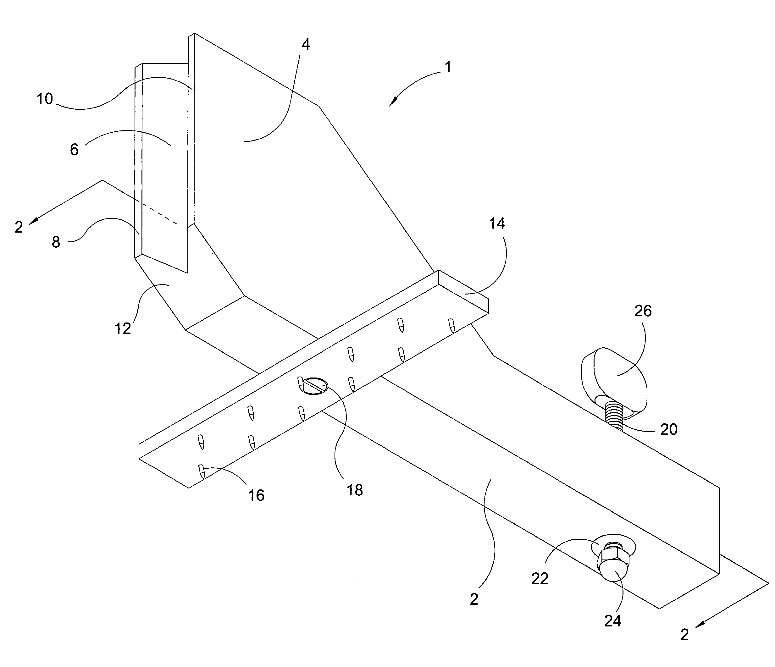
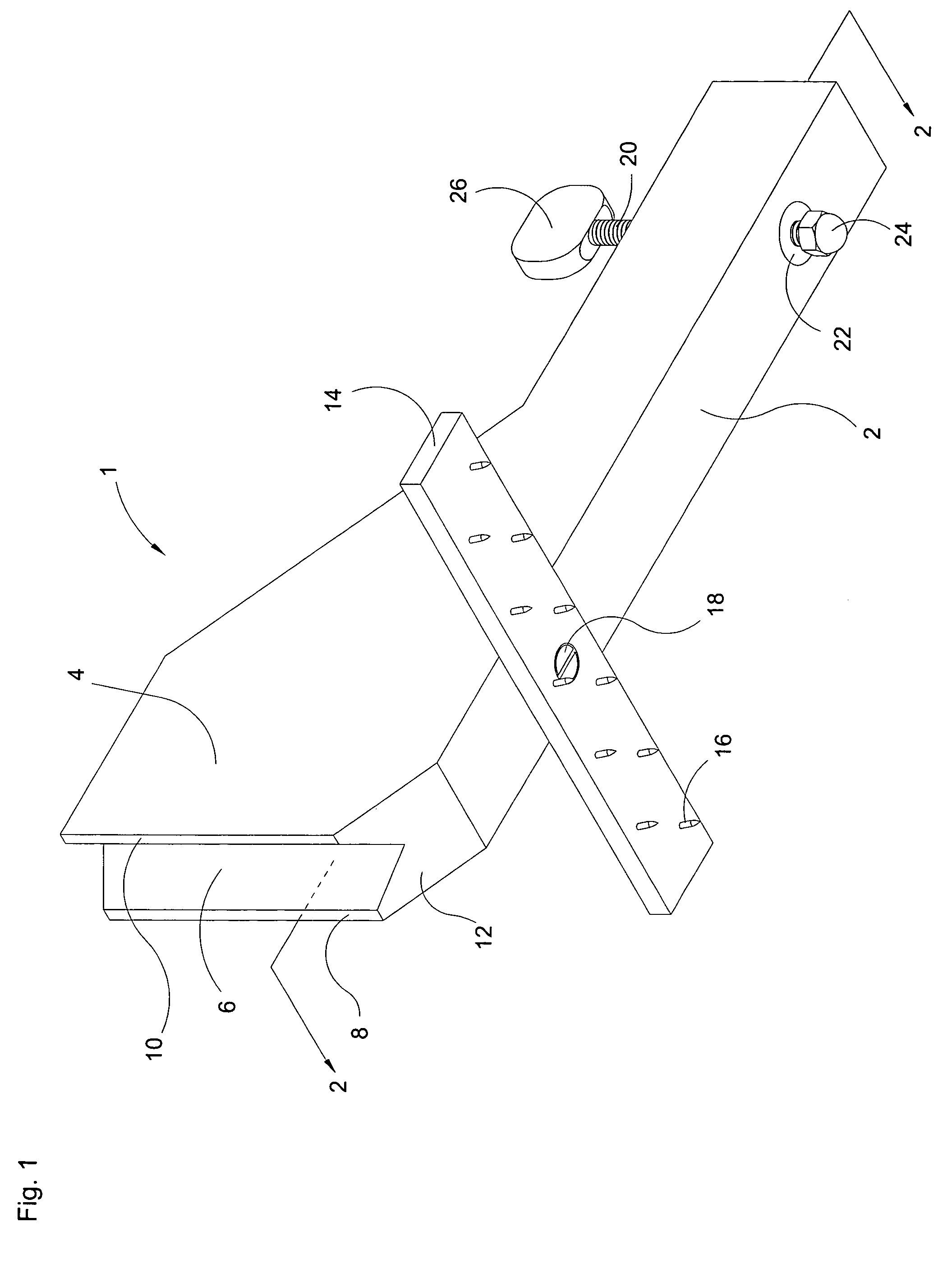
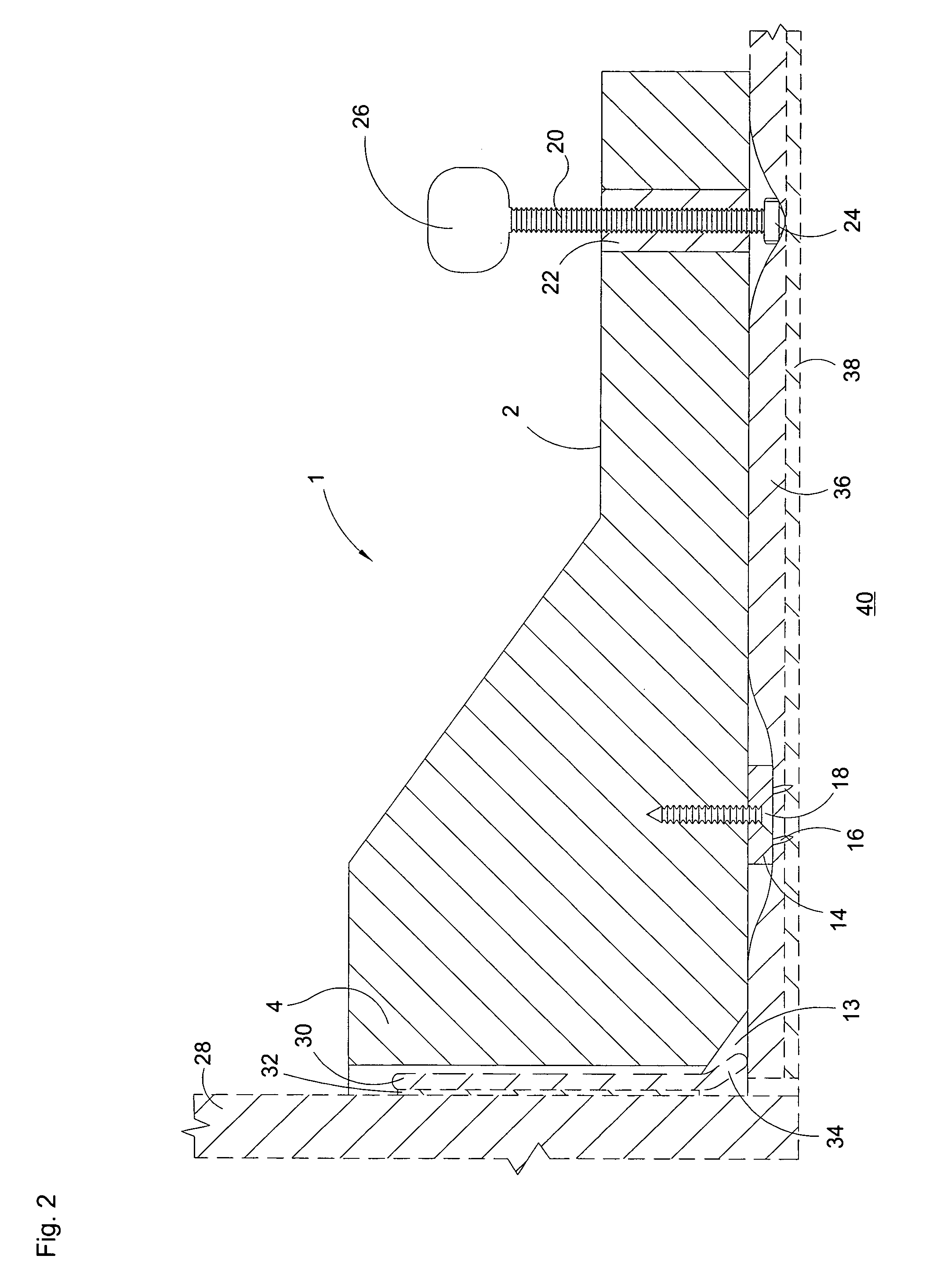
[0019]Referring now to the drawings, and in particular to FIG. 1, the instant inventive cove base molding clamping tool is referred to generally by Reference Arrow 1. The body of the cove base molding clamping tool 1 preferably comprises a wooden or plastic injection molded block having a rearwardly extending lever arm 2, and having an upwardly and forwardly extending molding driving arm 4. A carpet tack strip 14 having downwardly and rearwardly extending pins or tacks 16 preferably forms a “T” bar attachment located at the proximal ends of the driving and lever arms 2 and 4, such attachment preferably incorporating a helically threaded screw 18, and glue. The laterally extending “T” bar advantageously provides enhanced carpet gripping, provides resistance against lateral tipping of the clamp, and provides resistance against rotational slippage of the clamp about a vertical axis.

[0020]Referring further to FIG. 1, a carpet engaging foot preferably comprising a domed cap nut 24 is pre...


PUM


Abstract

A cove base molding clamp consisting of a carpet engaging fulcrum, a lever arm having proximal and distal ends, the proximal end of the lever arm being fixedly attached to the carpet engaging fulcrum; a driving arm having a proximal and a distal end, the proximal end of the driving arm being fixedly attached to the carpet engaging fulcrum; a carpet engaging foot; a jack screw interconnecting the carpet engaging foot and the distal end of the lever arm, the jack screw being adapted for alternately downwardly extending the carpet engaging foot from the lever arm and upwardly retracting the carpet engaging foot toward the lever arm; and a molding engaging head fixedly attached to or formed wholly with the distal end of the driving arm.

Description

FIELD OF THE INVENTION[0001]This invention relates to carpet flooring and wall trim installation tools. More particularly, this invention relates to tools and apparatus adapted for clamping or compressively applying flexible vinyl cove base moldings to wall surfaces at floor level.BACKGROUND OF THE INVENTION[0002]Where lengths of flexible vinyl cove base molding are applied by gluing to 90° outside corner wall surfaces, such moldings tend to elastically resist sharp bending at such corner and tend to cause the inner adhesion surfaces of such moldings to outwardly arcuately curve away from the wall surfaces at the corners. Such moldings' elastic resistance to sharp 90° bending commonly frustrates and prevents glue adhesion at the wall corner surfaces, undesirably resulting in an unsightly cove base molding installation.[0003]Heavy objects such as bricks placed in an angled resting manner against the cove base molding at such corners are known to be utilized to attempt to achieve clos...

Claims


Application Information

Patent Timeline
IPC IPC(8): B23Q3/02E04F21/00
CPCE04F21/0069
Inventor SCHWIND, CARL L.
Owner SCHWIND CARL L
Learn More