Connector having improved contacts with fusible members

a technology of fusible members and connectors, applied in the field of electrical connectors, can solve the problems of increasing precision, increasing input/output density requirements, and increasing problems, and achieve the effect of reliably connecting a connector to a substrate and greater co-planarity

Active Publication Date: 2005-11-29
SAMTEC
View PDF94 Cites 53 Cited by
  • Summary
  • Abstract
  • Description
  • Claims
  • Application Information

AI Technical Summary

Benefits of technology

[0016]In order to overcome the unsolved problems of the prior art described above, preferred embodiments of the present invention provide an electrical connector that al

Problems solved by technology

One problem with miniaturized electrical connectors arises from the increased precision of placement necessary to produce the proper positioning and connection of the connector contacts or terminals onto the device.
This problem is exacerbated by the ever increasing input/output (I/O) density requirements demanded of the progressively smaller electrical connectors by increasingly miniaturized electrical devices.
With increased pin counts (e.g., greater number of terminals) in each connector, it becomes more and more difficult to maintain desired levels of co-planarity while maintaining contact of all of the terminals to a substrate or PCB.
However, arrayed connectors present attachment difficulties regarding connection to devices (i.e., circuit boards or substrates) since most of the contacts or terminals must necessarily be positioned in the interior of the two-dimensional array area and are accordingly difficult to align upon connection, visually inspect, and/or repair.
However, the use of a BGA has many disadvantages.
First of all, the use of solder balls greatly complicates the connector manufacturing process because an additional reflow step is required and the use of special equipment is also required.
A further problem may occur when the solder balls are attached to gold-plated tail portions of the contacts or terminals, during which process the gold of the tail portions of the contacts or terminals can mix with the tin/lead of the reflowed solder ball which can cause problems with gold embrittlement.
In addition to the above-described problems, variations in the dimensions and/or placement of solder balls at the interface can lead to an uneven or non-coplanar interface and intermittent or poor electrical contact.
Also, the presence of oversized or extra solder balls present in the connector interface, or the uncontrolled spreading of the solder balls during the multiple reflow steps can result in shorted connections and degraded connector performa

Method used


Image

  • Connector having improved contacts with fusible members
  • Connector having improved contacts with fusible members
  • Connector having improved contacts with fusible members

Examples


Embodiment Construction

[0058]Preferred embodiments of the present invention will now be described with reference to the drawings.

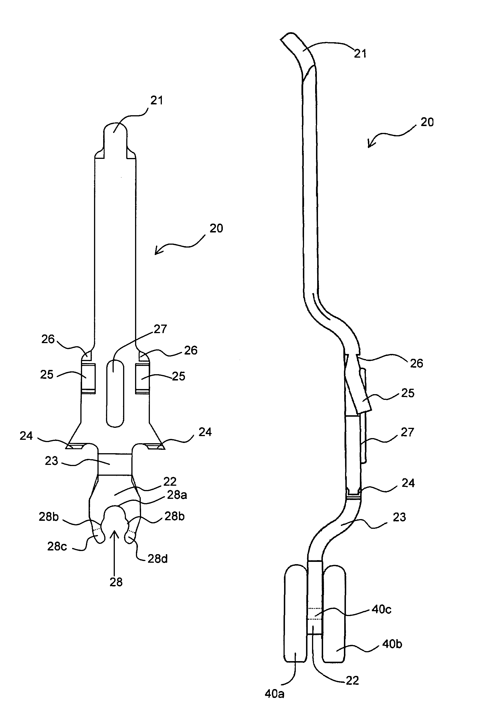
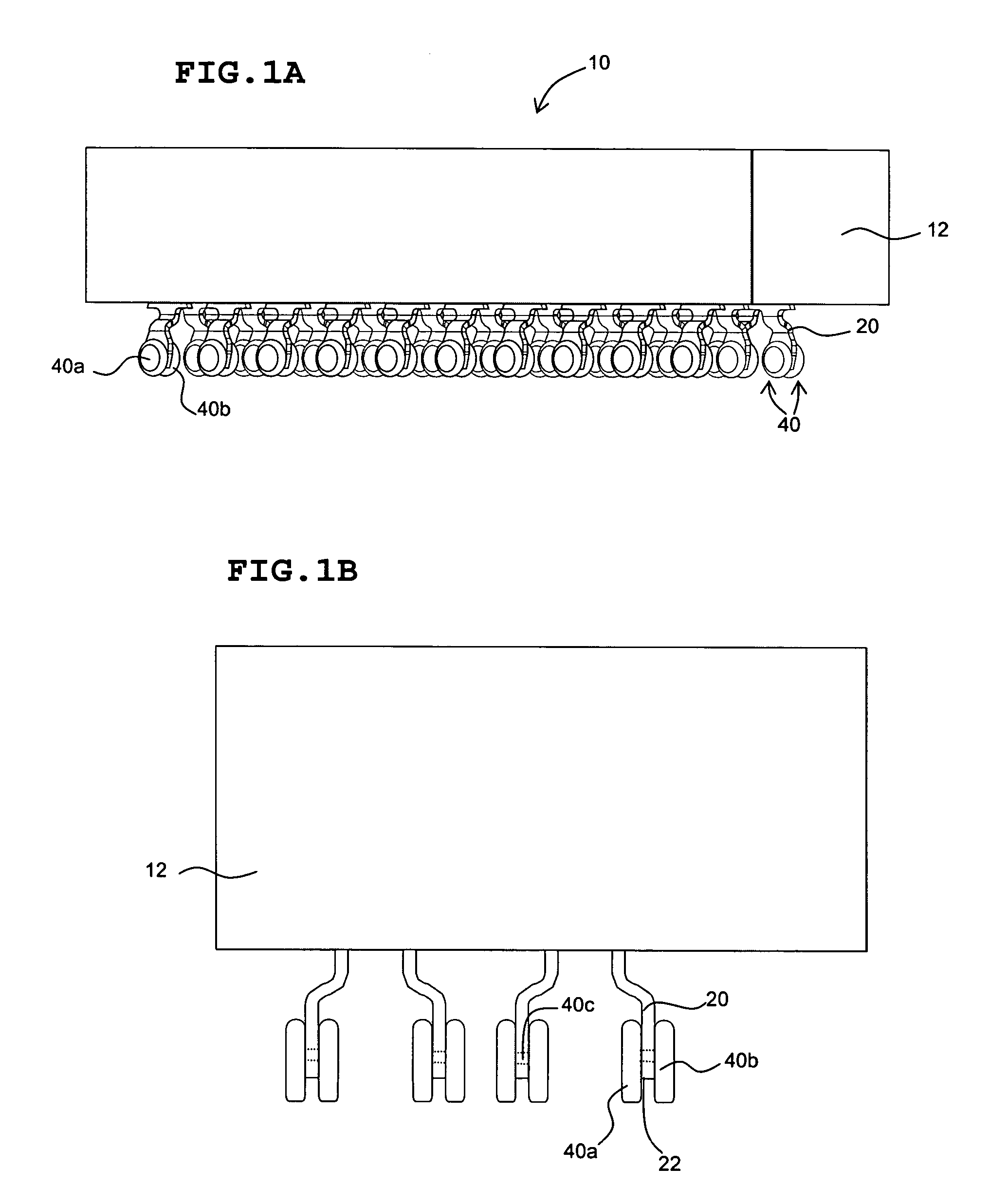
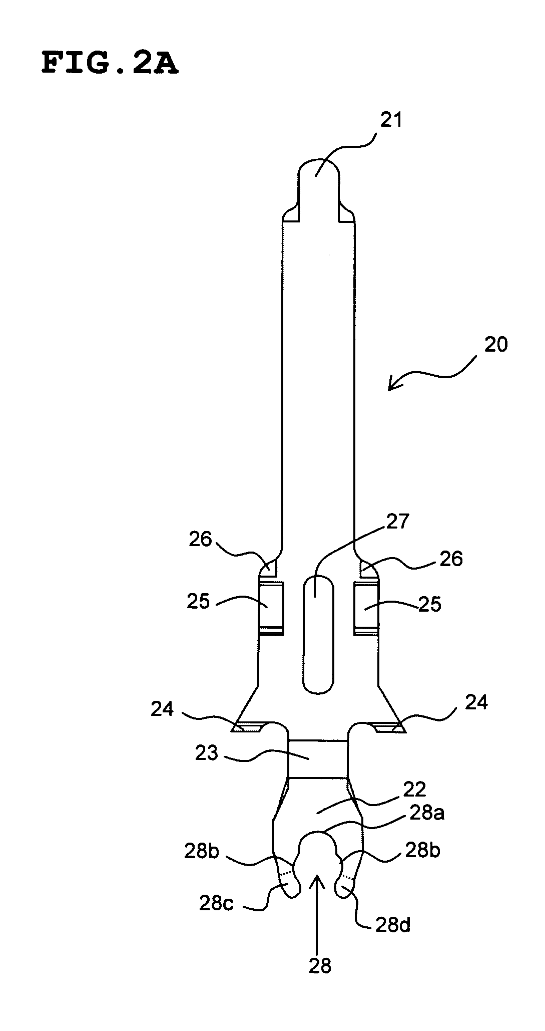
[0059]FIG. 1A is an isometric view and FIG. 1B is an end view of a connector 10 according to a first preferred embodiment of the present invention. The connector 10 includes a body 12 that is preferably made of an insulating material such as plastic, a plurality of cores (not shown in FIGS. 1A and 1B, but shown as element 14 in FIG. 9 which illustrates another preferred embodiment of the present invention) formed in the connector body 12 for receiving a plurality of contacts, and a plurality of contacts or terminals 20 inserted into the cores and held in the body 12. It should be noted that the connector 10 is shown in FIGS. 1A and 1B in a state before being reflowed to be attached to a substrate such as a PCB.

[0060]As seen in FIGS. 1A and 1B, each of the contacts or terminals 20 includes a fusible member 40 that is fixed to a tail portion 22 of the contact 20. It should be note...


PUM

PropertyMeasurementUnit
Distanceaaaaaaaaaa
Distanceaaaaaaaaaa
Electrical conductivityaaaaaaaaaa

Abstract

An electrical connector includes a connector body, a plurality of cores and a plurality of electrically conductive contacts disposed in the cores of the connector body. Each of the contacts includes a fusible member attached thereto. Each of the fusible members includes an intermediate portion and two support members disposed on opposite sides of the intermediate portion. The support members are arranged to hang down below a tail portion of the contacts.

Description

[0001]This application is a Continuation application of prior application Ser. No. 10 / 876,740, filed Jun. 28, 2004, now abandoned.BACKGROUND OF THE INVENTION[0002]1. Field of the Invention[0003]The present invention relates to electrical connectors and more specifically, the present invention relates to connectors having a unique arrangement of contacts or terminals having a fusible member attached thereto, that allows for much higher coplanarity while simplifying the connector manufacturing and assembly procedures.[0004]2. Description of the Related Art[0005]Electrical connectors are used to place electrical devices, such as printed circuit boards, in communication with one another. An electrical connector may be thought of as having two portions, one portion of which connects to a first electrical device and the second portion of which connects to a second electrical device to be put into communication with the first device. To connect the two devices, the two portions of the elec...

Claims


Application Information

Patent Timeline
IPC IPC(8): H01R4/02H01R12/00H01R12/57H01R43/02H05K3/34
CPCH01R12/57H01R43/0235H01R43/0256H05K3/3426Y10T29/49149H05K2201/10984Y10T29/49147Y02P70/50
Inventor MONGOLD, JOHN A.KOOPMAN, STEPHEN P.
Owner SAMTEC
Why Eureka
Try Eureka