Display apparatus using organic electroluminescent element and manufacturing method thereof

a technology of electroluminescent elements and manufacturing methods, applied in the direction of electric discharge tubes/lamps, identification means, instruments, etc., can solve the problems of reducing the aperture rate of the apparatus, and achieve the effects of stable light emission characteristics, effective utilization, and expansion of the region of light-emitting elements of organic electro-luminescent elements

Inactive Publication Date: 2005-11-29
JOLED INC
View PDF7 Cites 101 Cited by
  • Summary
  • Abstract
  • Description
  • Claims
  • Application Information

AI Technical Summary

Benefits of technology

[0024]According to the aspect of the invention, the area of a pixel can be effectively utilized and the region, which contributes to light emitting, of an organic electro-luminescent element can be enlarged by forming a barrier plate in a contact region for connecting the organic electro-luminescent element belonging to an upper layer portion and a wiring belonging to a lower layer portion. A stable light emitting characteristics can be obtained by enlarging the region contributing to light emitting.

Problems solved by technology

Therefore, the downside light taking out structure has a problem that the aperture rate thereof is reduced, wherein the aperture rate is defined by dividing an effective display area with unit pixel area.

Method used


Image

  • Display apparatus using organic electroluminescent element and manufacturing method thereof
  • Display apparatus using organic electroluminescent element and manufacturing method thereof
  • Display apparatus using organic electroluminescent element and manufacturing method thereof

Examples


Embodiment Construction

[0034]Hereafter, the drawings are referred while an embodiment of the present invention is described in detail.

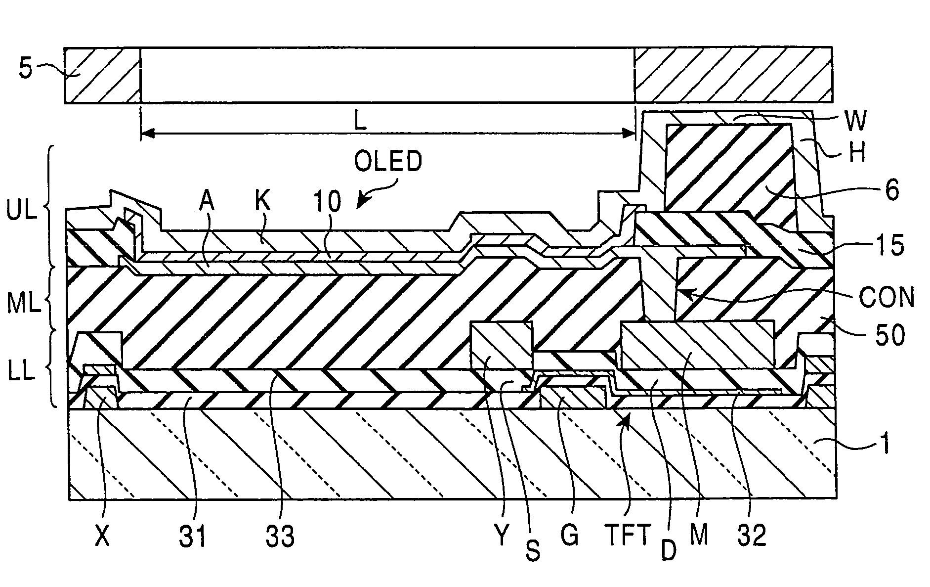
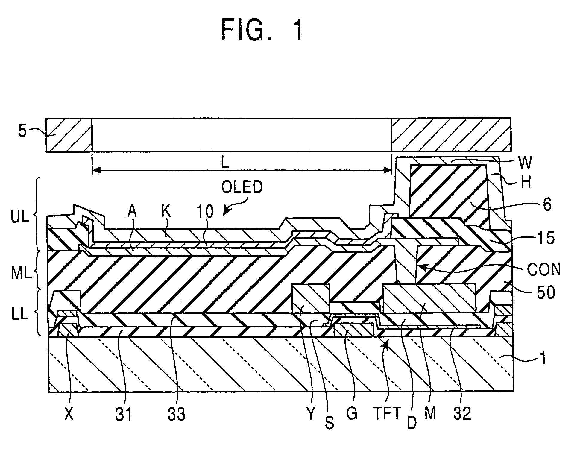
[0035]FIG. 1 is an example of a partial sectional view showing the structure of a display apparatus according to the present invention. FIG. 1 shows one of pixels of the display apparatus.

[0036]As shown in FIG. 1, the display apparatus includes a substrate 1, a pixel formed on the substrate 1, and a barrier plate 6 for separating the pixel from adjoining pixels. The pixel is separated to be a lower layer portion LL, a middle layer portion ML and an upper layer portion UL from the bottom side in the order. The lower layer portion LL includes a wiring such as a data wiring Y and a connecting wiring M formed on the substrate 1. The upper layer portion UL includes an organic electro-luminescent element OLED. The middle layer portion ML electrically insulates the lower layer portion LL and the upper layer portion UL from each other. The middle layer portion ML comprises an inter...


PUM


Abstract

A display apparatus includes a substrate, a plurality of pixels formed on the substrate, and a barrier plate for separating adjoining pixels from each other. Each pixel includes a lower layer portion having wiring formed on the substrate, an upper layer portion having an organic electro-luminescent element, and a middle layer portion for insulating the lower layer portion and the upper layer portion from each other electrically. The organic electro-luminescent element is connected with the windings through a contact hole formed in the middle layer portion. The barrier plate is disposed in the upper layer portion so as to overlap with a region including a contact hole not suitable for forming the organic electro-luminescent element.

Description

[0001]This application is a divisional application of application No. 09 / 711,880; filed: Nov. 15, 2000, now U.S. Pat. No. 6,614,174BACKGROUND OF THE INVENTION[0002]1. Field of the Invention[0003]The present invention relates to a display apparatus using an organic electro-luminescent element and a manufacturing method thereof. In particular, the invention relates to a technique for improving a display apparatus using an organic electro-luminescent element, emitted light of which is taken out of its upper surface on its cathode side, to have a larger aperture rate.[0004]2. Description of the Related Art[0005]An organic electro-luminescent element may be utilized as a pixel of, for example, an active matrix type display apparatus. An organic electro-luminescent display apparatus using an organic electro-luminescent element as its pixel is regarded as a promising next generation flat panel display apparatus in place of a liquid crystal display apparatus.[0006]FIG. 7 shows a structure o...

Claims


Application Information

Patent Timeline
Patent Type & Authority Patents(United States)
IPC IPC(8): G09F9/30G09F9/00H01L27/32H01L51/50H05B33/00H05B33/10H05B33/12H05B33/14H05B33/22H05B33/26
CPCH01L27/3246H01L51/5036H01L51/5218H01L2251/5315H10K59/122H10K50/125H10K50/818H10K2102/3026H05B33/00
Inventor URABE, TETSUOSASAOKA, TATSUYASEKIYA, MITSUNOBUYAMAGISHI, MACHIO
Owner JOLED INC
Why Eureka
Try Eureka