Measurement of angle rotation using microstrip resonators (2.4ghz,2 degree)

a microstrip resonator and angle detection technology, applied in the direction of waveguides, instruments, waveguides, etc., can solve the problems of relatively short service life and high cost of production, and achieve the effect of robustness, economical and easy to produ

Inactive Publication Date: 2005-11-29
ROBERT BOSCH GMBH
View PDF11 Cites 1 Cited by
  • Summary
  • Abstract
  • Description
  • Claims
  • Application Information

AI Technical Summary

Benefits of technology

[0003]The measuring device of the invention for contactless detection of an angle of rotation or a torsional rotation has the advantage over the prior art that it uses a change in a resonant frequency for instance, as a measure for ascertaining the angle of rotation or the torsional rotation. A first resonator and a second resonator are provided, and at feast one resonator is connected to the rotating element (such as a shaft) whose angle of rotation is to be determined. The resonators have an essentially circular circumference. Furthermore, at least on protrusion and / or one recess is embodied on the circumference of the respective resonators, and the resonators are coplanar to one another. Via the exciter device, the resonators are excited, and upon a rotation of the resonators relative to one another, the positions of the protrusions and the recesses of the resonators changes, and as a result, the respective resonant frequency changes as well. This change in the resonant frequency is a measure for a change in the angle of rotation or torsional rotation. However, it is also possible to determine the amplitude of the signal, backscattered by the resonators, at a fixed frequency (such as a frequency at the edge of the resonator curve) and to use it as a measure of the angle of rotation or the torsional rotation. Thus in accordance with the invention, very small angular changes in particular can be detected.
[0004]Preferably, the two resonators are embodied annularly. As a result, a simple structure and ease of production of the measuring device of the invention are attainable.
[0009]Preferably, the resonators are produced from printed circuit board material, with a metallization applied over it. As a result, the production costs for the measuring device of the invention can be kept low. However, it is also possible instead of the printed circuit board material to use a ceramic material, for instance. In the choice of material, it is important that a nonconductive material be used as the substrate material of the metallization.
[0011]To make especially high precision possible, that is, the measurement of very small angles, the resonators in an outset position are disposed in such a way relative to one another that slits formed in the resonators are located in the same place, which is perpendicular to the resonators.
[0015]According to the invention, a robust, easy to produce and economical measuring device, particularly for small angles, is thus made available. The measuring device of the invention is preferably used on steering linkages, or to ascertain the position of the throttle valve.

Problems solved by technology

In these sensors based on the principle of magnetism, it is disadvantageous that they are based on a complicated layer technology and their structure is relatively complicated, making them very expensive to produce.
The optical sensors, conversely, are quiet vulnerable to soiling and can therefore be used only conditionally in the motor vehicle, for instance, and have a relatively short service life, since they are often used under extreme conditions.

Method used


Image

  • Measurement of angle rotation using microstrip resonators (2.4ghz,2 degree)
  • Measurement of angle rotation using microstrip resonators (2.4ghz,2 degree)
  • Measurement of angle rotation using microstrip resonators (2.4ghz,2 degree)

Examples


Embodiment Construction

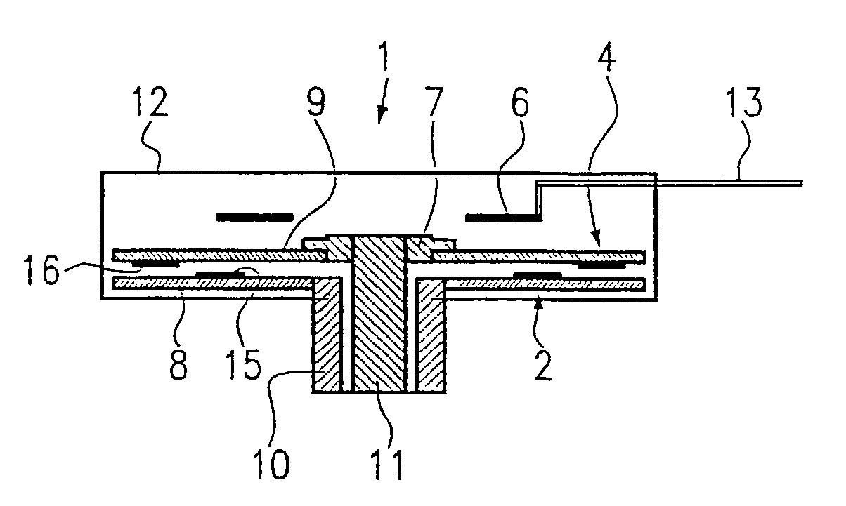
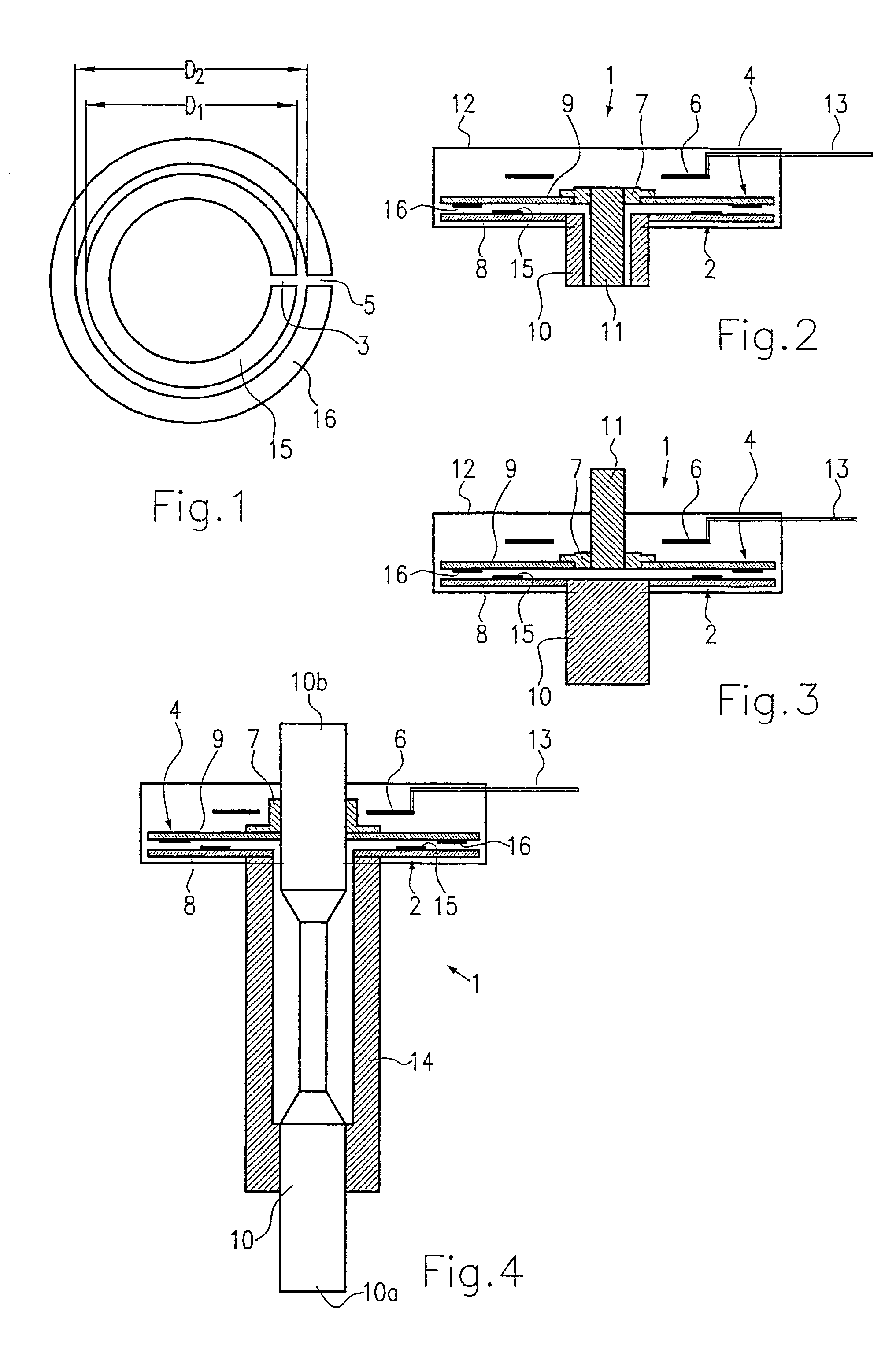
[0030]In FIGS. 1 and 2, a first measuring device of the invention for contactless detection of an angle of rotation is shown. The measuring device 1 includes a first resonator 2 and a second resonator 4. The resonators 2 and 4 each comprise a respective substrate plate 8 and 9 and a metallization 15 and 16 applied over it (see FIG. 2). The substrate plates 8, 9 are made from a printed circuit board material. As shown in FIG. 1, the metallization 15 of the first resonator 2 has a slit 3, and the metallization 16 of the second resonator 4 has a slit 5. In FIG. 1, the two annularly embodied metallizations 15, 16 of the resonators 2 and 4 are shown in their outset position. It should be noted that besides the outset position shown in FIG. 1, outset positions with slits rotated relative to one another are also possible. An enhanced sensitivity can thus be achieved. Furthermore, with slits rotated relative to one another, the direction of rotation is also easily measurable.

[0031]The two r...


PUM

PropertyMeasurementUnit
resonant frequencyaaaaaaaaaa
frequencyaaaaaaaaaa
diameteraaaaaaaaaa

Abstract

The present invention relates to a measuring device and a method for contactless detection of an angle of rotation or a torsional rotation. The measuring device includes a first resonator (2) and a second resonator (4). The two resonators (2, 4) have an essentially circular circumference, on which at least one protrusion and / or one recess is disposed. The two resonators (2, 4) are coplanar to one another and are also rotatable relative to one another. In addition, an exciter device (6) for exciting the resonators and a receiver device (6) for measuring a backscattered signal are present. Upon a relative rotation of the two resonators (2, 4) to one another, the resonant frequency changes, which is used as a measure for ascertaining the angle of rotation.

Description

BACKGROUND OF THE INVENTION[0001]The present invention relates to a device and a method for contactless detection of an angle of rotation or a torsional rotation. In particular, the present invention relates to a device and a method for contactless detection of very small angles or very small torsional rotations.[0002]Measuring devices for contactless detection of angles of rotation, such as torque sensors, are known in the most various embodiments. Such measuring devices are sometimes based on different principles. For instance, optical sensors are known that detect the angle of rotation via a code placed on the rotating part. Magnetic sensors are also known, in which a magnetically generated field changes as a function of the angle of rotation, and this change can be used as a measure for the angle of rotation. In these sensors based on the principle of magnetism, it is disadvantageous that they are based on a complicated layer technology and their structure is relatively complica...

Claims


Application Information

Patent Timeline
Patent Type & Authority Patents(United States)
IPC IPC(8): G01B7/24G01B15/00G01D5/20G01D5/48G01L1/25G01L3/00G01L3/10H01P1/203
CPCG01B7/24G01D5/48G01L1/25G01L3/10
Inventor NEUMANN, CHRISTIANSCHMIDT, RALF
Owner ROBERT BOSCH GMBH
Why Eureka
Try Eureka