Digital architecture for radio-frequency apparatus and associated methods

a digital architecture and radio-frequency technology, applied in the field of digital architecture for can solve the problems of exacerbated interference among the various blocks of transceiver circuitry, no known technique for addressing all of the above problems in high-performance rf receivers or transceivers, and baseband processor circuitry that does not contain their own channelization filtering

Inactive Publication Date: 2005-11-29
SILICON LAB INC
View PDF64 Cites 42 Cited by
  • Summary
  • Abstract
  • Description
  • Claims
  • Application Information

AI Technical Summary

Benefits of technology

[0031]FIG. 17A shows a conceptual or functional block diagram that provides more details of a receiver digital circuitry according to the invention.
[0032]FIG. 17B illustrates a conceptual or functional block diagram that provides more details of a receiver digital circuitry according to the invention that includes programmable-gain amplifier circuitries.
[0033]FIG. 18A depicts a conce

Problems solved by technology

From the perspective of the transceiver's circuitry, RF transceivers typically include sensitive components susceptible to noise and interference with one another and with external sources.
Integrating the transceiver's circuitry into one integrated circuit may exacerbate interference among the various blocks of the transceiver's circuitry.
Unfortunately, no known technique for addressing all of the above issues in high-performance RF receivers or transceivers, for example, RF transceivers used in cellular and t

Method used


Image

  • Digital architecture for radio-frequency apparatus and associated methods
  • Digital architecture for radio-frequency apparatus and associated methods
  • Digital architecture for radio-frequency apparatus and associated methods

Examples


embodiment 400

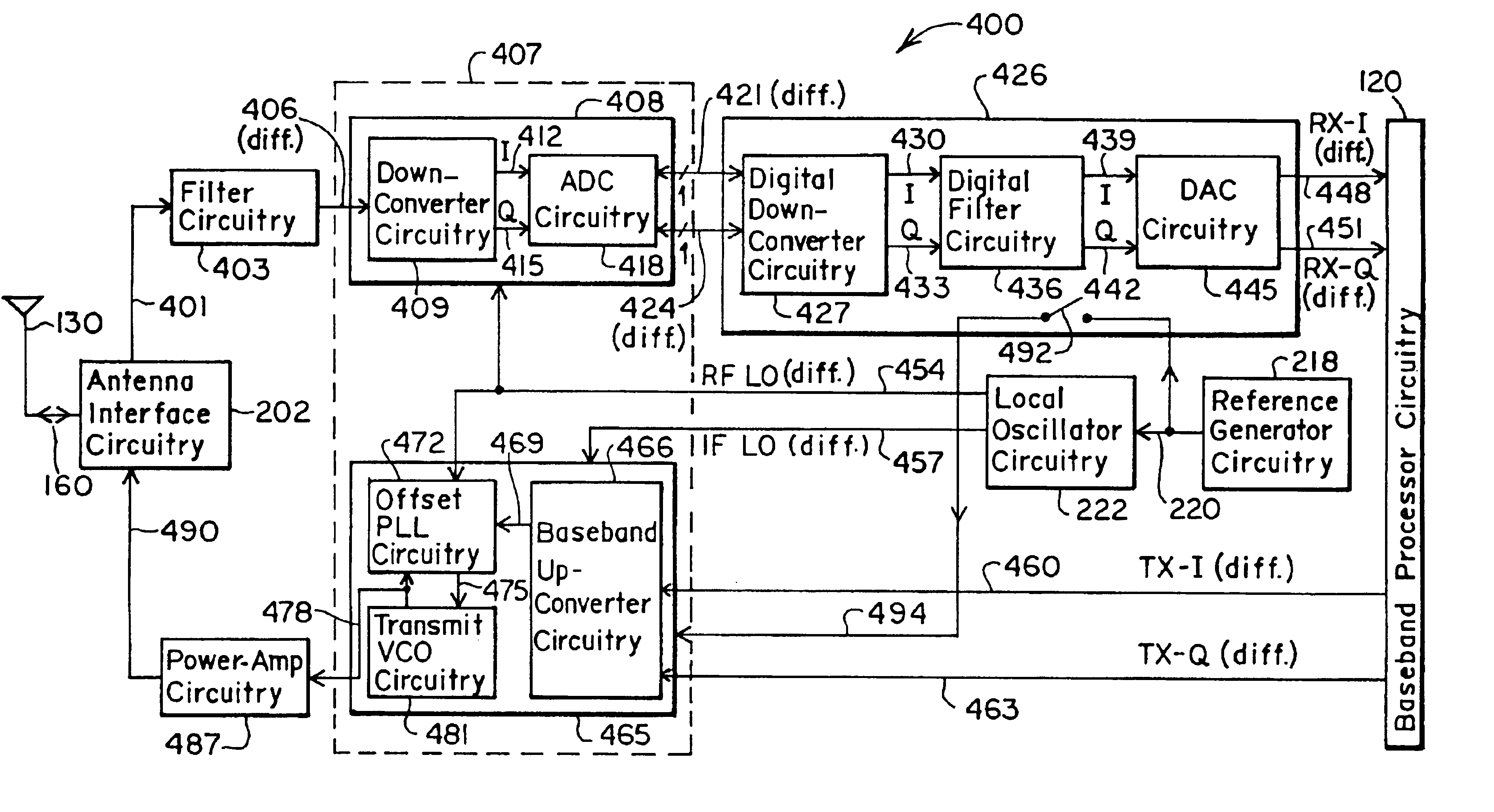
[0087]FIG. 4 shows a more detailed block diagram of an embodiment 400 of an RF transceiver partitioned according to the invention. The transceiver includes receiver analog circuitry 408, receiver digital circuitry 426, and transmitter circuitry 465. In the receive mode, the antenna interface circuitry 202 provides an RF signal 401 to a filter circuitry 403. The filter circuitry 403 provides a filtered RF signal 406 to the receiver analog circuitry 408. The receiver analog circuitry 408 includes down-converter (i.e., mixer) circuitry 409 and analog-to-digital converter (ADC) circuitry 418. The down-converter circuitry 409 mixes the filtered RF signal 406 with an RF local oscillator signal 454, received from the local oscillator circuitry 222. The down-converter circuitry 409 provides an in-phase analog down-converted signal 412 (i.e., I-channel signal) and a quadrature analog down-converted signal 415 (i.e., Q-channel signal) to the ADC circuitry 418.

[0088]The ADC circuitry 418 conve...

embodiment 700

[0107]Because the embodiment 700 includes the function of the receiver digital circuitry 426 within the baseband processor circuitry 120, it includes two circuit partitions, or circuit blocks. A first circuit partition 710 includes the receiver analog circuitry 408 and the transmitter circuitry 465. A second circuit partition comprises the local oscillator circuitry 222. Note also that, similar to the RF transceiver shown in FIG. 2C, one may also include within the baseband processor circuitry 120 the functionality of the reference generator circuitry 218, as desired.

[0108]FIG. 8 shows an embodiment 800 of a multi-band RF transceiver, partitioned according to the invention. Preferably, the RF transceiver in FIG. 8 operates within the GSM (925 to 960 MHz for reception and 880-915 MHz for transmission), PCS (1930 to 1990 MHz for reception and 1850-1910 MHz for transmission), and DCS (1805 to 1880 MHz for reception and 1710-1785 MHz for transmission) bands. Like the RF transceiver in F...

embodiment 800

[0129]Like the transceiver in FIG. 4, if the receiver digital circuitry 851 need not be compatible with the common analog interface to baseband processors, one may remove the DAC circuitry 875A and 875B, and use a digital interface to the baseband processor circuitry 120, as desired. In fact, similar to the RF transceiver shown in FIG. 2D, one may realize the function of the receiver digital circuitry 851 within the baseband processor circuitry 120, using hardware, software, or a combination of hardware and software. In that case, the RF transceiver would include two circuit partitions, or circuit blocks. The first circuit partition 801 would include the receiver analog circuitry 839 and the transmitter circuitry 877. A second circuit partition would comprise the local oscillator circuitry 222. Note also that, similar to the RF transceiver shown in FIG. 2C, in the embodiment 800, one may include within the baseband processor circuitry 120 the functionality of the reference generator...


PUM


Abstract

A radio-frequency (RF) receiver includes a receiver analog circuitry and a receiver digital circuitry. The receiver analog circuitry resides within a first integrated circuit and the receiver digital circuitry resides within a second integrated circuit. The second integrated circuit couples to the first integrated circuit via a one-bit digital interface. The receiver analog circuitry receives an RF signal and processes the received RF signal to generate a digital signal. The receiver analog circuitry provides the digital signal to the receiver digital circuitry. The receiver digital circuitry includes a digital down-converter circuitry that mixes the digital signal with an intermediate frequency (IF) local oscillator (LO) signal to generate a digital down-converted signal. The receiver digital circuitry also includes a digital filter circuitry that filters the digital down-converted signal to generate a filtered digital signal.

Description

CROSS-REFERENCE TO RELATED APPLICATIONS[0001]This patent application is a continuation-in-part of U.S. patent application Ser. No. 09 / 821,342, titled “Partitioned Radio-Frequency Apparatus and Associated Methods,” and filed on Mar. 29, 2001 now U.S. Pat. No. 6,804,497. This patent application claims priority to Provisional U.S. Patent Application Ser. No. 60 / 261,506, filed on Jan. 12, 2001; Provisional U.S. Patent Application Ser. No. 60 / 273,119, titled “Partitioned RF Apparatus with Digital Interface and Associated Methods,” and filed on Mar. 2, 2001; and Provisional U.S. Patent Application Ser. No. 60 / 333,520, filed on Nov. 27, 2001.[0002]Furthermore, this patent application incorporates by reference the following patent documents: U.S. patent application Ser. No. 10 / 075,099, “Notch Filter for DC Offset Reduction in Radio-Frequency Apparatus and Associated Methods”; and U.S. patent application Ser. No. 10 / 074,676, title “DC Offset Reduction in Radio-Frequency Apparatus and Associa...

Claims


Application Information

Patent Timeline
IPC IPC(8): H04B1/28H04B1/40H04B15/02H04B15/04
CPCH04B1/0003H04B1/28H04B1/38H04B1/406H04B15/02H04B15/04H04B2215/064
Inventor BEHRENS, RICHARD T.PAULUS, TODSPURBECK, MARK S.SRINIVASAN, VISHNU S.KERTH, DONALD A.SCOTT, JEFFREY W.TUTTLE, G. TYSONVISHAKHADATTA, G. DIWAKAR
Owner SILICON LAB INC
Why Eureka
Try Eureka