Data communication and control for medical imaging systems
Inactive Publication Date: 2005-11-29
BAJER MEDIKAL KEHA INK
View PDF22 Cites 124 Cited by
Summary
Abstract
Description
Claims
Application Information
AI Technical Summary
This helps you quickly interpret patents by identifying the three key elements:
Problems solved by technology
Method used
Benefits of technology
[0018]The communication interface of the present invention is a substantial improvement over previous systems that merely communicated timing information via relay closures. In the present invention, data transmission includes information sent between devices regarding operating parameters, operator input, device status information, and/or control sequencing. In addition, data transferred from one device to another device in the present invention can be used to enable active control of the receiving device from that data. For example, during the injecting state, data transmission from an ultrasound imager can be sent to an injector to enable active control of the injection flow rate based on the data received. Currently available systems merely relay analog closures between an injector and an imager to communicate the timing of certain states and are not used for data transmission
Problems solved by technology
For example, a portion of the information available from the raw signal may be lost or distorted in various compressi
Method used
Image
Click on the blue label to locate the original text in one second.
Reading with bidirectional positioning of images and text.
Examples
example
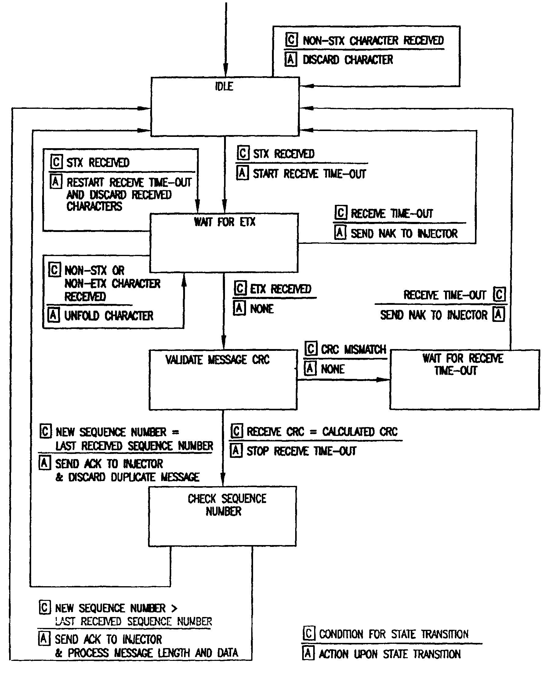
[0118]In one embodiment, injector subsystem 15a periodically transmits status information through subsystem interface 90c to imager subsystem 15b, which preferably only has to acknowledge the successful (or unsuccessful) data reception. In this embodiment, imager subsystem 15b does not request data from injector subsystem 15a or send data other than acknowledgements to injector subsystem 15a. A message based flow control mechanism is preferably used to regulate the data flow from injector subsystem 15a.
[0119]In this embodiment, only two different messages are preferably sent from injector subsystem 15a to imager subsystem 15b. The injector subsystem interface status message preferably contains the interface software version number and indicates if injector status information is available, and the injector status message preferably contains, for example, injection parameter values and volume information. The injector subsystem interface status message is preferably transmitted when ...
PUM
Abstract
A system for producing a contrast-enhanced medical image of a patient includes a source of a contrast or enhancement medium, a pressurizing unit in fluid connection with the source of contrast or enhancement medium, an energy source operable to apply energy to a region of the patient, an imaging unit providing a visual display of an internal view of the patient based upon a signal resulting from the energy applied to the region of the patient, and a control unit. In an embodiment, the signal is affected by a condition of the contrast or enhancement medium in the patient. To control the procedures, the control unit adjusts the condition of the contrast or enhancement medium in the patient based upon the signal. A communication interface preferably enables information between an injector subsystem and an imaging subsystem.
Description
CROSS-REFERENCE TO RELATED APPLICATIONS[0001]The present application is a divisional of U.S. patent application Ser. No. 09 / 300,326, filed on Apr. 27, 1999, now U.S. Pat. No. 6,397,098 which is a continuation-in-part of U.S. patent application Ser. No. 09 / 197,773, filed on Nov. 23, 1998, now U.S. Pat. No. 6,385,483 which is a divisional of U.S. patent application Ser. No. 08 / 309,820, filed on Sep. 21, 1994, now U.S. Pat. No. 5,840,026, the disclosures of which are incorporated herein by reference.BACKGROUND OF THE INVENTION[0002]The present invention relates generally to data communication and control, and, more particularly, to devices, systems and methods for communication of data and control based thereon in contrast-enhanced medical imaging systems.[0003]It is well recognized that the appropriate dose for many medications is related to a number of variables, including, for example, the size, weight, or physiologic state of the patient being treated. This variation is readily app...
Claims
Application Information
Patent Timeline
Application Date:The date an application was filed.
Publication Date:The date a patent or application was officially published.
First Publication Date:The earliest publication date of a patent with the same application number.
Issue Date:Publication date of the patent grant document.
PCT Entry Date:The Entry date of PCT National Phase.
Estimated Expiry Date:The statutory expiry date of a patent right according to the Patent Law, and it is the longest term of protection that the patent right can achieve without the termination of the patent right due to other reasons(Term extension factor has been taken into account ).
Invalid Date:Actual expiry date is based on effective date or publication date of legal transaction data of invalid patent.
Inventor UBER, III, ARTHUR E.RHINEHART, EDWARD J.ALMON-MARTIN, ROSEMARYGRIFFITHS, DAVID M.HIRSCHMAN, ALAN D.SCIULLI, FRANCIS J.GRUMSKI, WALTERPAGANO, VERAZELENSKI, KAREN