
Power tool with portable power source

a power tool and portable technology, applied in the field of power tools, can solve the problems of unbalanced and cumbersome operation of tools, unbalanced tools render it difficult to work evenly on workpieces, and unbalanced tools, so as to facilitate enhanced gripping for control of power tools, maintain control over power tools, and facilitate effective two-handed grips

Inactive Publication Date: 2005-12-06
JPW IND
View PDF81 Cites 41 Cited by
  • Summary
  • Abstract
  • Description
  • Claims
  • Application Information

AI Technical Summary

Benefits of technology

[0012]The power tool may also include an outer elastomer surface, such as an elastomer injected overmolding, to facilitate enhanced gripping for control over the power tool. The handle may also be generally U-shaped to allow an operator a range of locations about the housing to facilitate an effective two-handed grip to maintain control over the power tool. In one embodiment, the handle may be designed with first and second end portions that are enlarged with respect to the remainder of the handle in order to provide the operator with a variety of grip sizes to choose from.
[0013]The power tool may also include an actuator electrically connected to the motor for activating and deactivating the power tool. The actuator may be positioned in a bridging member which connects the handle and the housing of the power tool, or may be recessed in the bridging member connecting the handle and the housing of the power tool in order to prevent accidental actuating thereof.

Problems solved by technology

This often tends to make the tool unbalanced and cumbersome to operate due to the unbalanced and oversized weight distribution.
For example, a 14.4-volt or 18-volt battery located at the end of a power tool handle increases the weight distribution such that the tool becomes difficult to hold and operate steady for appropriate periods of time due to operator fatigue.
Experience also has revealed that an unbalanced tool renders it difficult to work evenly on a workpiece.
If the power tool is unbalanced, the task of working the tool evenly about the workpiece becomes more difficult for the operator and has the tendency to make the tool work heavier on the side nearest the battery (the heavier portion of the tool).
This compounds the difficulty and discomfort in holding the tool.
The enlarged handle configuration tends to render the power tool more difficult and uncomfortable to handle.
An even further shortcoming with handle-mounted batteries is the limitation on the ability to provide a variety of gripping locations.
For example, the addition of a battery pack to the handle often shortens the length of the portion of the handle on which one can grip.
Since a wide variety of individuals will be using the power tool, the shortcomings from having the battery pack in the handle make it difficult to meet the variety of demands each operator may have for the power tool.

Method used


Image

  • Power tool with portable power source
  • Power tool with portable power source
  • Power tool with portable power source

Examples


Embodiment Construction

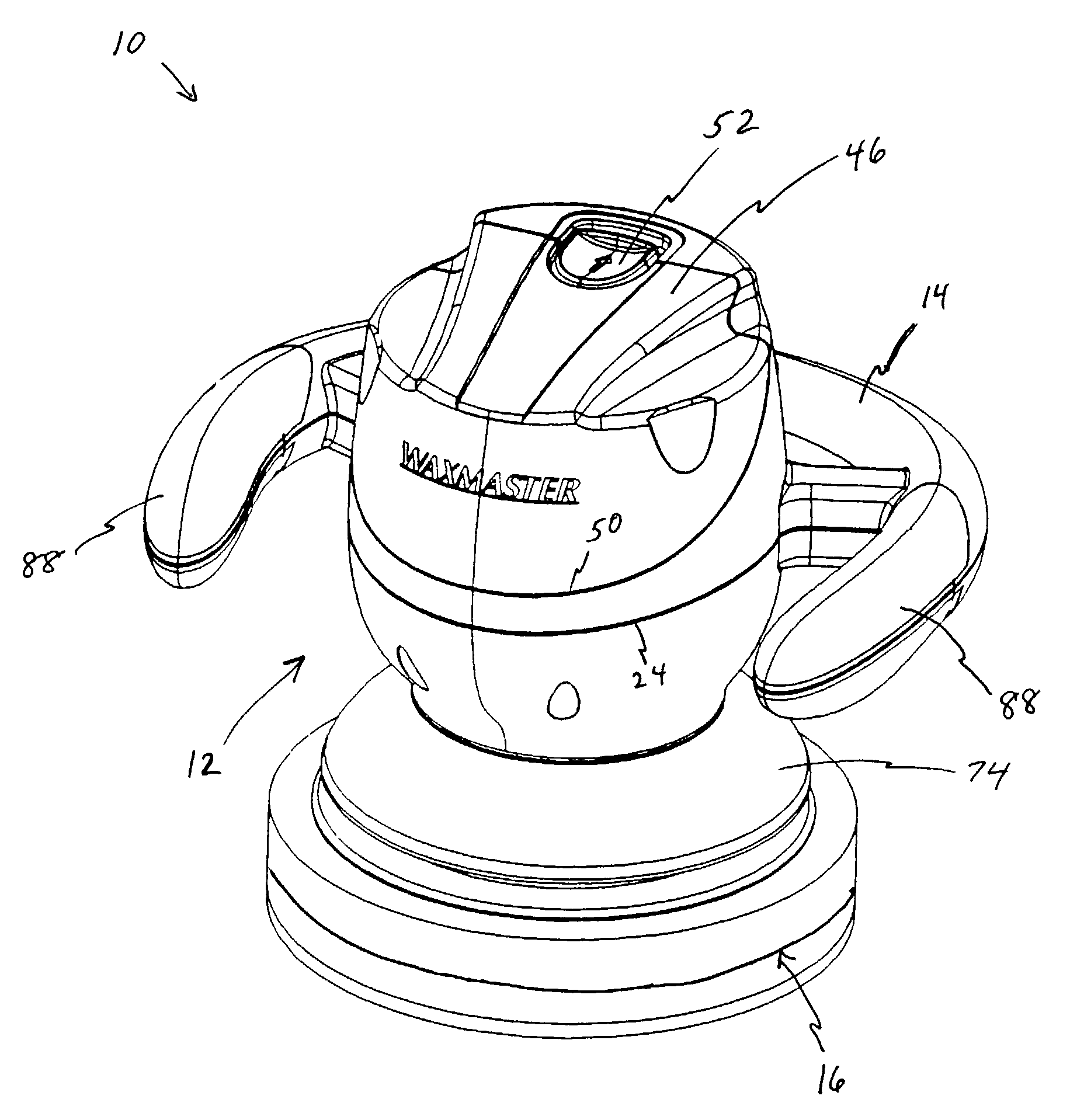
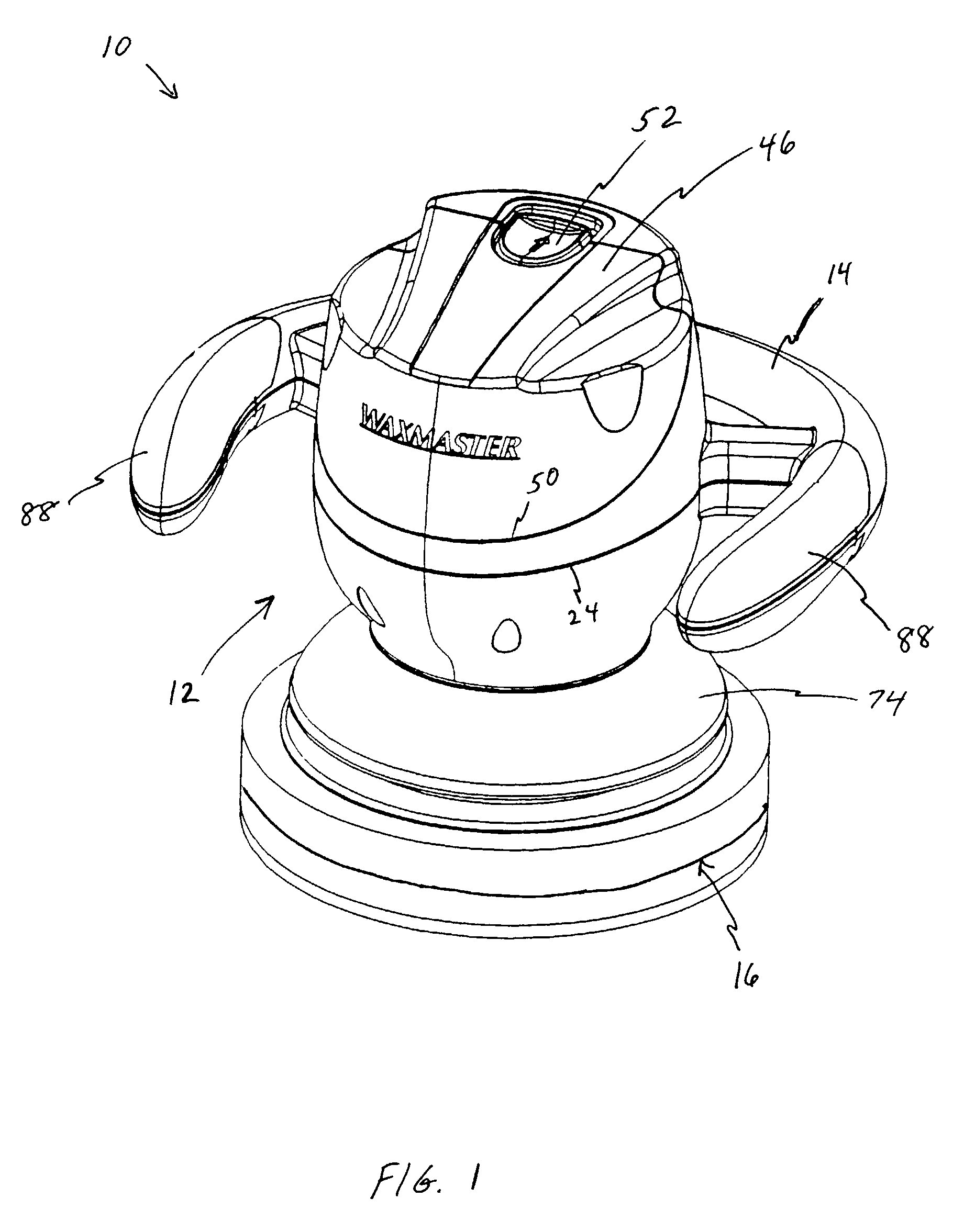
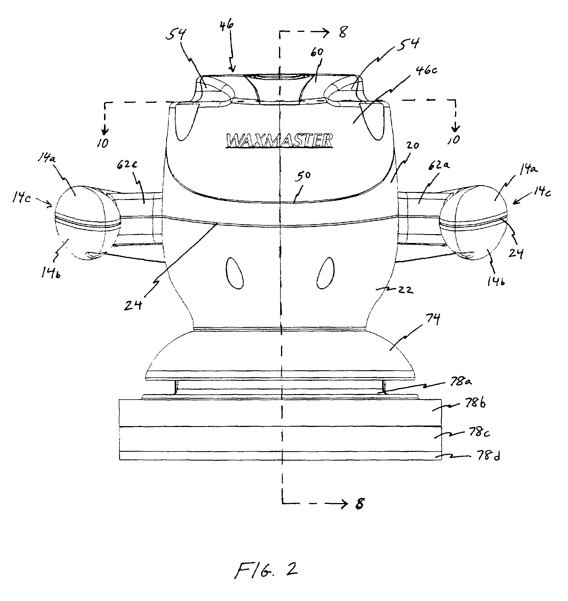
[0033]In FIGS. 1–10, there is illustrated a power tool 10 with a portable power source for working on a workpiece (e.g., waxing, buffing, polishing, etc.) in accordance with the present invention. The power tool 10 includes a housing 12, a generally U-shaped handle 14 connected to the housing 12, and a work element, such as a pad 16, for working on a desired workpiece, such as the body of a automobile or hull of a boat. The power tool 10 includes a symmetrical design about a vertical reference plane (not shown) extending centrally from a forward end 18a to a rearward end 18b (see FIGS. 3 and 4). The cross section illustrated in FIG. 8 is taken along the vertical reference plane.

[0034]The housing 12 includes an upper housing shell 20 and a lower housing shell 22 which, when connected to each other, interface along a part line 24. The upper housing shell 20 and lower housing shell 22 can be made of any suitably lightweight material and are preferably molded plastic parts. The upper ho...


PUM


Abstract

A power tool in accordance with the invention includes a housing having an internal compartment with a motor therein, a handle connected to the housing for maneuvering the power tool, a working element connected to and driven by the motor to work on a workpiece, and a removable, portable power source having a first position wherein the power source is located primarily in the internal compartment of the housing and being electrically connected to the motor to provide power to the motor for driving the working element and a second position wherein the power source is located remotely from the housing and detached electrically from the motor. A preferred embodiment of the tool also includes a lock associated with the apparatus which has a lock position that prevents the removable, portable power source from unintentionally becoming separated from the power tool, and an unlock position that enables the removable portable power source to be selectively removed from the internal compartment of the housing and separated from the power tool. A preferred embodiment of the power tool includes the use of a rechargeable, removable, portable power source and an electrical connector which allows the power tool to be powered by an alternate power source located externally of the power tool.

Description

FIELD OF THE INVENTION[0001]This invention relates generally to a power tool having a removable, portable power source and, more particularly to a hand held polisher having a removable, portable power source in association with its housing.BACKGROUND OF THE INVENTION[0002]The tool industry offers a variety of cordless power tools for performing work on various types of workpieces. Each of these tools offer the advantage of being operated without a cord and / or remote from a generator or a hard wired power source, such as a conventional outlet. For example, cordless power tools allow the tool operator to use the tool without regard for both the proximity to a power outlet or to the length of available power. Battery-powered tools also allow the tool operator to operate the tool without interference and distracting concerns associated with an attached power cord.[0003]Known power tools commonly locate the battery at the handle of the tool. This often tends to make the tool unbalanced a...

Claims


Application Information

Patent Timeline
Patent Type & Authority Patents(United States)
IPC IPC(8): B24B23/00B24B23/02B24B29/00B24B31/12B25F5/02
CPCB24B23/00B24B29/00B25F5/02
Inventor BOYER, CHRISTOPHER T.
Owner JPW IND
Features
  • Generate Ideas
  • Intellectual Property
  • Life Sciences
  • Materials
  • Tech Scout
  • Unparalleled Data Quality
  • Higher Quality Content
  • 60% Fewer Hallucinations
Learn More