
A/D converter calibration

a converter and calibration technology, applied in the field of analog-to-digital converters, can solve the problems of limited performance, ideal effects, limited maximum achievable accuracy-speed performance of any a/d converter, etc., and achieve the effect of improving the utilization of the resolution of calibrating d/a converters and increasing the overall accuracy of a/d converters

Inactive Publication Date: 2005-12-06
INFINEON TECH AG
View PDF15 Cites 94 Cited by
  • Summary
  • Abstract
  • Description
  • Claims
  • Application Information

AI Technical Summary

Benefits of technology

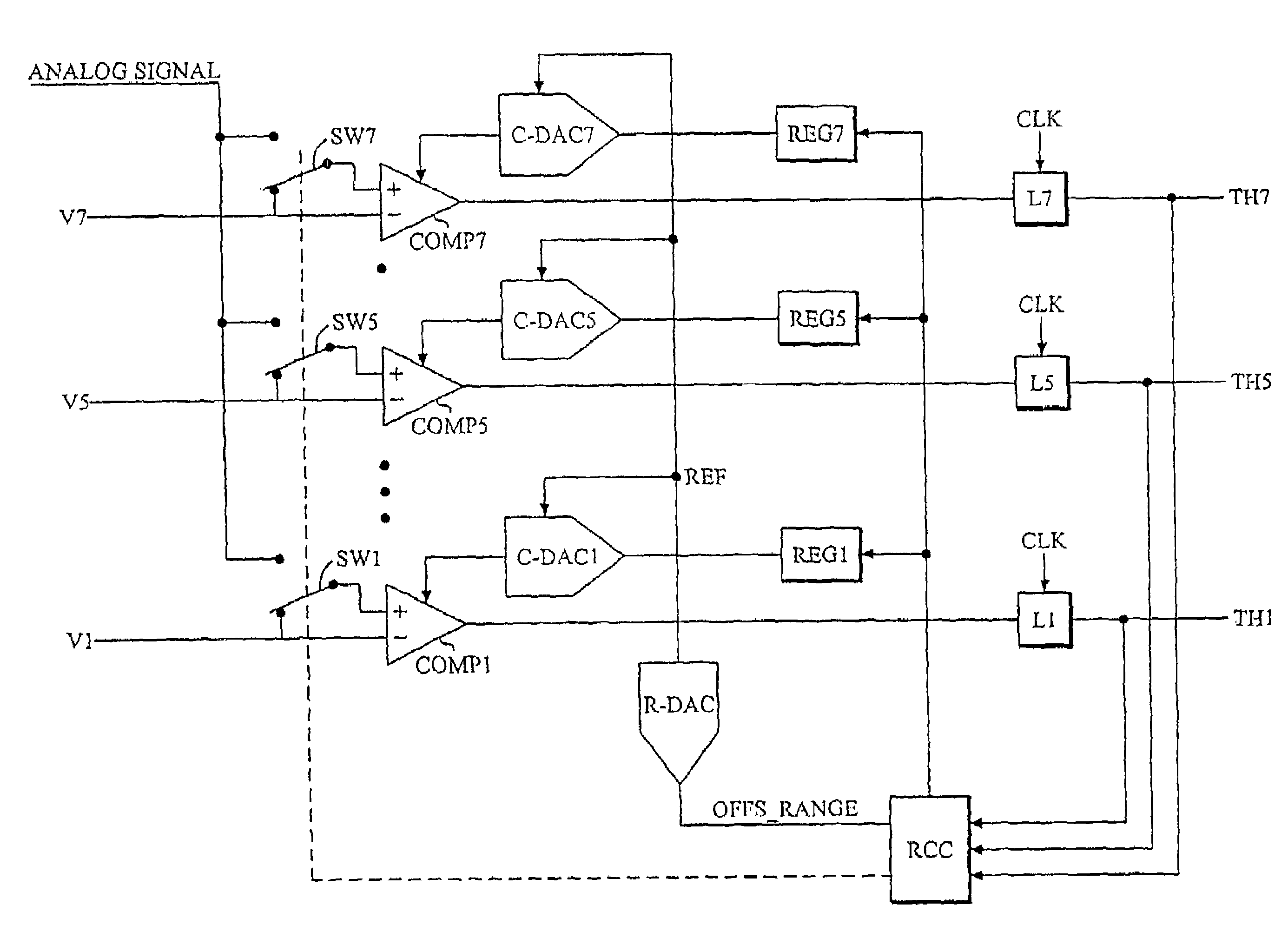
[0005]An object of the present invention is to improve the utilization of the calibrating D / A converter resolution in flash type A / D converters or sub-converters to increase the overall A / D converter accuracy and to guarantee that no errors supersede the calibrating D / A converter range.
[0006]This object can be achieved by a method of improving accuracy of an A / D converter structure including a set of comparators with associated calibrating D / A converters, comprising the steps of determining a measure of the offset error range for the entire set of comparators; and adjusting the dynamic range of each calibrating D / A converter to the determined measure.
[0011]Briefly, the present invention determines the offset error range for the entire set of comparators and thereafter adjusts the dynamic range of each calibrating D / A converter to the determined offset error range. This maximizes utilization of the resolution of the calibrating D / A converters.

Problems solved by technology

The maximum achievable accuracy-speed performance of any A / D converter is limited by non-ideal effects associated with its building blocks.
Typically, the performance is limited by settling time, limited amplifier gain and component mismatch.
When designing high performance A / D converters, these limitations impose stringent demands on building blocks, leading to prolonged design time, lower yield and trade-offs between accuracy and speed.
However, the largest error amplitude that the calibration has to cope with may not be well known or vary strongly between different converters of the same type.
In some circumstances this will lead to an undesirable amount of extra chip area and resolution of calibrating D / A (digital-to-analog) converters.
Additionally, the implemented resolution of the calibrating D / A converters will not be fully utilized in cases where the actual error amplitudes are substantially less than the implemented calibration range.

Method used


Image

  • A/D converter calibration
  • A/D converter calibration
  • A/D converter calibration

Examples


Embodiment Construction

[0026]In the following description the same reference designations will be used for the same or similar elements.

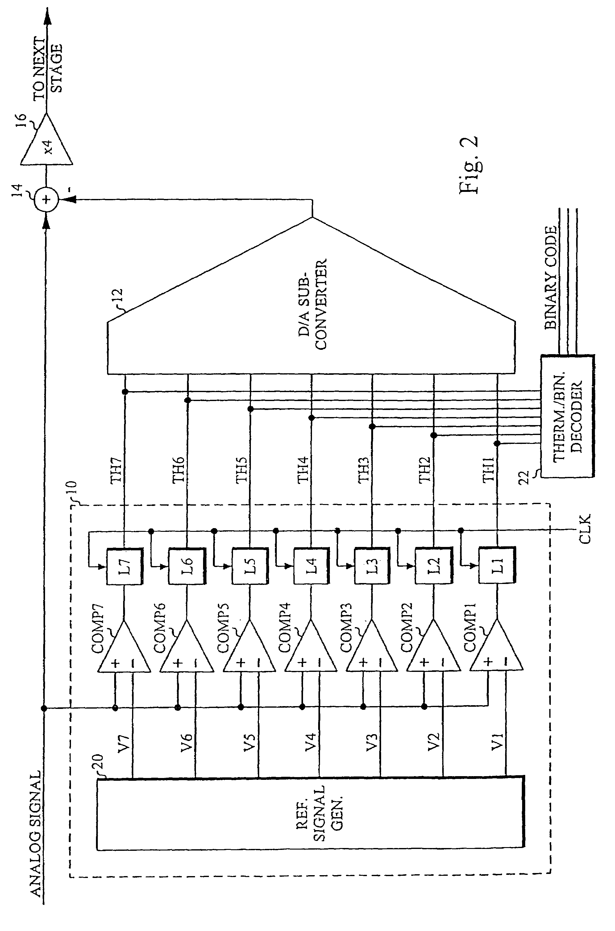
[0027]In this disclosure, a pipeline A / D converter will be used to illustrate the proposed range calibration method, but the method can also be applied to other types of converters, such as flash, sub-ranging, multi-bit delta-sigma and cyclic A / D converters or whenever a larger number of parallel offset calibrated comparators are used.

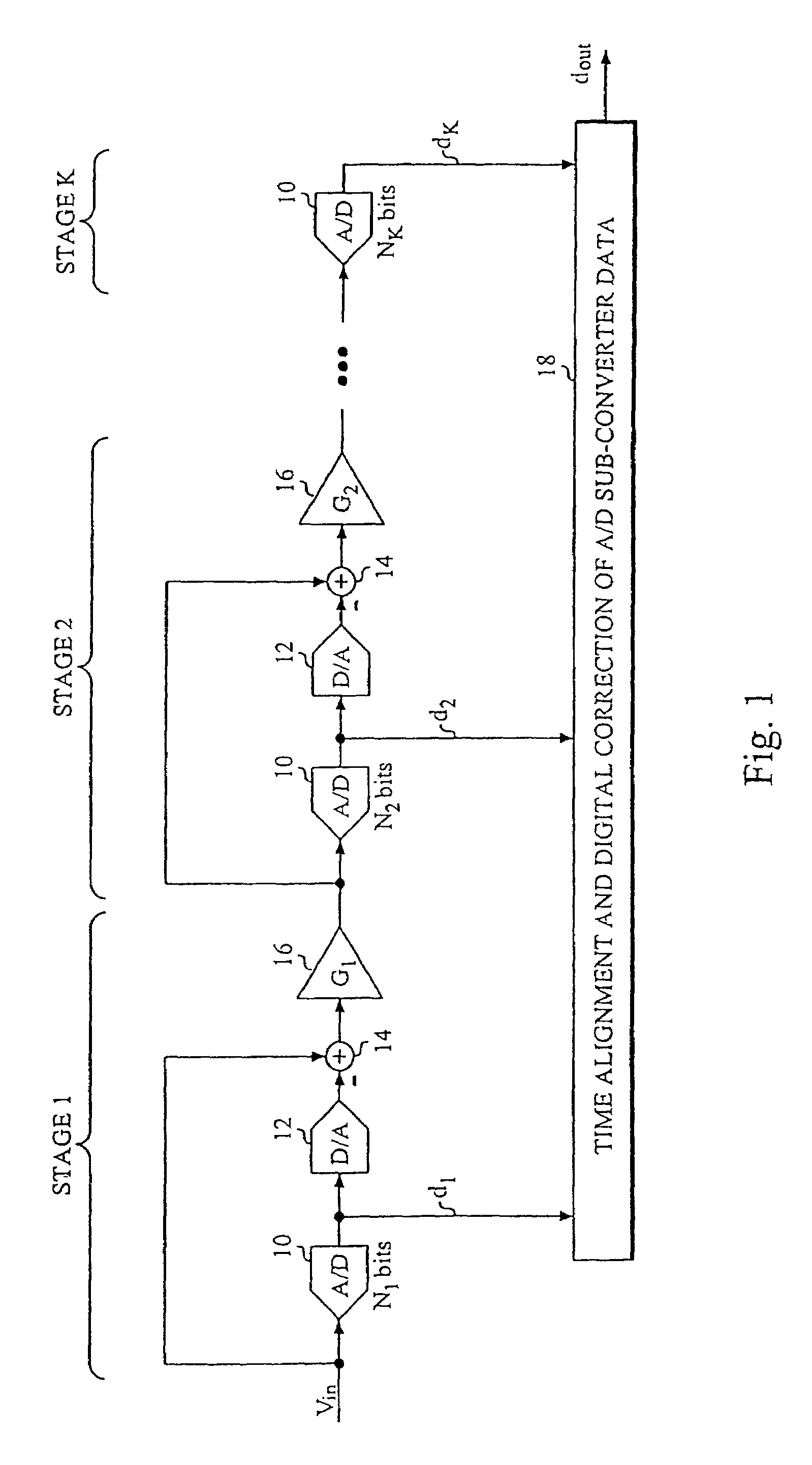
[0028]FIG. 1 is a block diagram of a typical pipeline A / D converter. An N-bit analog-to-digital conversion is performed in two or more stages, each stage extracting {N1, N2 . . . Nk} bits of information represented by the digital words {d1, d2 . . . dk}, where K is the number of pipeline stages. The first pipeline stage extracts the N1 most significant bits using an N1-bit A / D sub-converter 10. Then the estimated value is subtracted from the analog input signal Vin by using a D / A sub-converter 12 and an adder 14, leaving a residue containing...


PUM


Abstract

A D / A converter range calibration system in an A / D converter structure including a set of comparators with associated calibrating D / A converters includes means (RCC) for determining the offset error range for the entire set of comparators and means (R-DAC) for adjusting the dynamic range of each calibrating D / A converter to this offset error range.

Description

CROSS REFERENCE TO RELATED APPLICATION[0001]This application is a continuation of copending International Application No. PCT / SE03 / 00449 filed Mar. 17, 2003 which designates the United States, and claims priority to Swedish application no. 0200940-5 filed Mar. 25, 2002.TECHNICAL FIELD OF THE INVENTION[0002]The present invention relates to A / D (analog-to-digital) converters, and in particular how to improve the accuracy and yield of flash A / D converters or A / D sub-converters in pipeline, sub-ranging and cyclic A / D converters.BACKGROUND OF THE INVENTION[0003]The maximum achievable accuracy-speed performance of any A / D converter is limited by non-ideal effects associated with its building blocks. Typically, the performance is limited by settling time, limited amplifier gain and component mismatch. When designing high performance A / D converters, these limitations impose stringent demands on building blocks, leading to prolonged design time, lower yield and trade-offs between accuracy an...

Claims


Application Information

Patent Timeline
Patent Type & Authority Patents(United States)
IPC IPC(8): H03M1/10H03M1/36H03M1/70
CPCH03M1/1019H03M1/361H03M1/70
Inventor JANSSON, CHRISTER
Owner INFINEON TECH AG
Learn More