
Method for autostereoscopic display

a display method and autostereoscopic technology, applied in the field of autostereoscopic display, can solve problems such as not being able to compensa

Inactive Publication Date: 2005-12-06
ALIOSCOPY +1
View PDF6 Cites 24 Cited by
  • Summary
  • Abstract
  • Description
  • Claims
  • Application Information

AI Technical Summary

Benefits of technology

[0005]An object of the present invention is to provide a display method enabling the above-specified problem to be remedied, at least in part.
[0011]For example, in an image presenting a sloping line segment, the offset between the color components, e.g. red, green, and blue, of the pixels that follow one another in the “high definition” image and that is due to said distribution in space of the original information about the various display pixels, is, in the presence of contrast, perceived by the brain more as a high resolution difference in brightness than as a periodic variation in color. In addition, the spatial distribution of color points has the effect that the two eyes, which see two different viewpoints, generally see different color components through a given lens, thus inducing complementarity from one eye to the other which attenuates perception of the low resolution of the color components. The overall subjective effect is an improvement in the fineness of the image and in the perception of planes (due to the increase in disparity resolution), and the lower color resolution is practically not perceived.
[0014]This makes it possible to benefit from the improvement in image definition that can be obtained by modern methods for processing images digitally. In particular, said lower definition can be the definition of the screen, thus making it possible in particular to start from standard video images.
[0019]It is advantageous, in particular when said lower definition is screen definition to increase definition by generating an intermediate autostereoscopic image having increased definition that is lower than said high definition, and from which said high definition autostereoscopic image is generated. This applies in particular when p=3 and the increased definition image has p−1 (i.e. two) times as many pixels as the starting autostereoscopic image, whereas the high definition autostereoscopic image has p=3 times as many pixels as the starting autostereoscopic image.

Problems solved by technology

The methods described in the documents mentioned above do not make it possible to compensate, at least in part, the loss of definition due to the presence of N viewpoints.

Method used


Image

  • Method for autostereoscopic display
  • Method for autostereoscopic display
  • Method for autostereoscopic display

Examples


Embodiment Construction

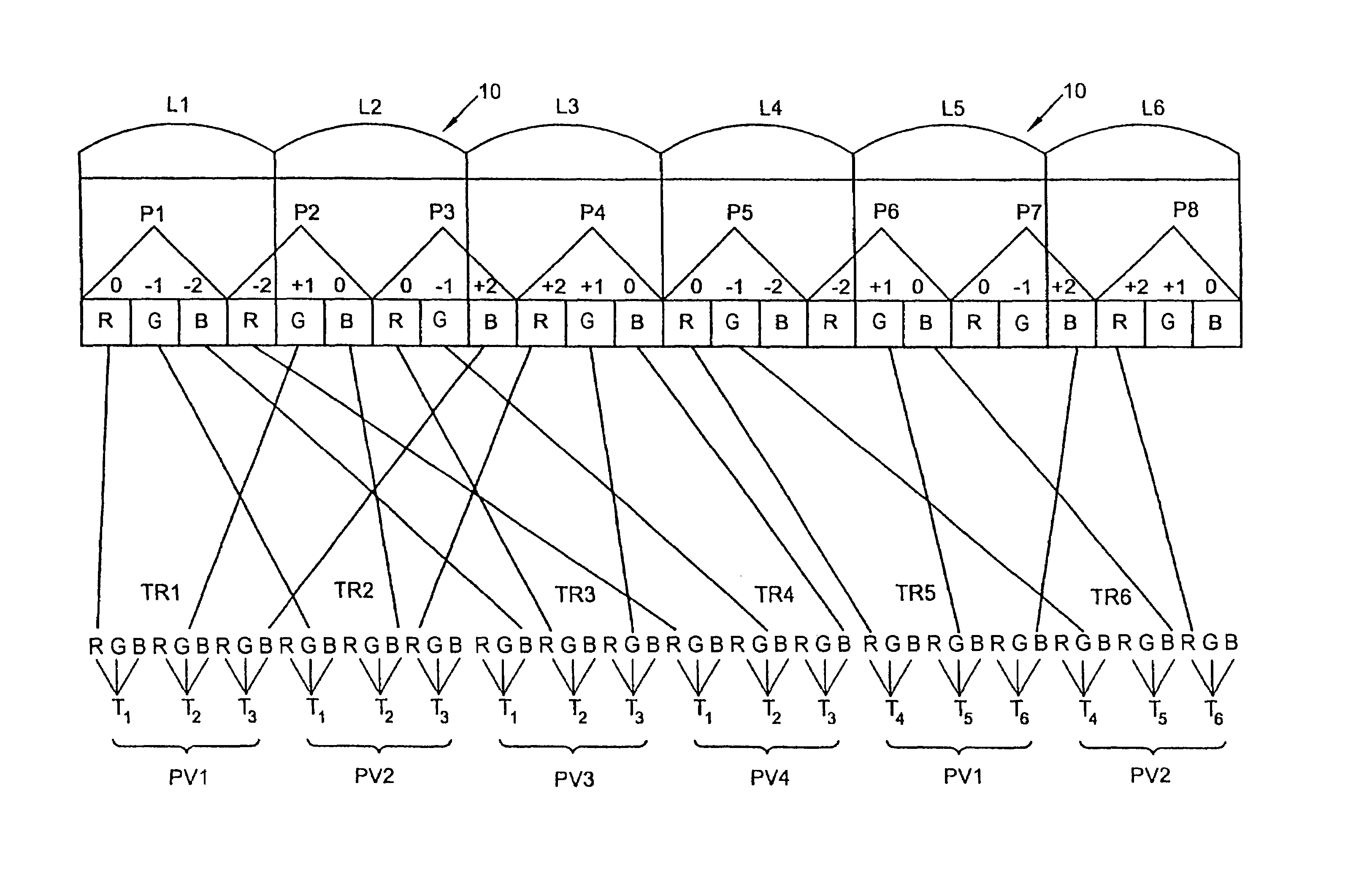
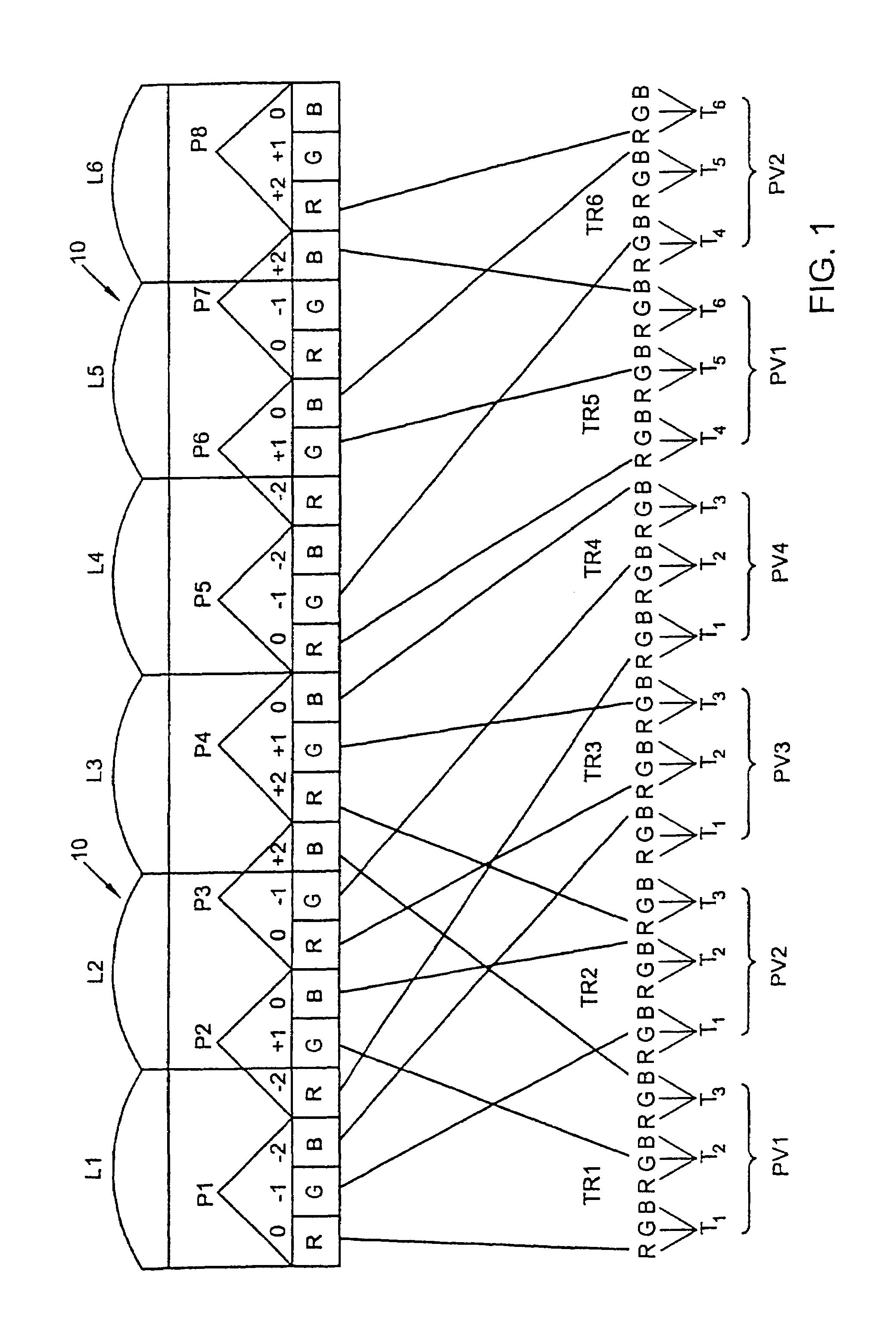
[0039]In FIG. 1, corresponding to N=4 and p=3, the high definition image has three times as many pixels in the row direction as the standard image used in FIG. 1a of PCT application WO 94 / 26072. To facilitate description, it is shown in the form of an interleaved image comprising, in the row direction, groups of p=3 pixels, i.e. the three first pixels T1, T2, T3 of the first viewpoint PV1, the first three pixels T1, T2, T3 of the second viewpoint PV2, the first three pixels T1, T2, T3 of the third viewpoint PV3, the three first pixels T1, T2, T3 of the fourth viewpoint PV4, and then the next three pixels T4, T5, T6 of PV1, the next three pixels T4, T5, T6 of PV2, etc.

[0040]In the row direction the screen presents display pixels P1, P2, P3, . . . , PM, each made of p=3 color points corresponding to the red R, green G, and blue B color components. The lens array 10 has lenses L1, L2, L3, . . . at a pitch equal to four times the pitch of the color points in the display pixels, which me...


PUM


Abstract

The invention relates to a method of autostereoscopically displaying an N-viewpoint image on a screen having display pixels disposed in rows and columns, each display pixel presenting p>1 color points, corresponding to first, second, . . . , and pth color components, in which method the pixels of an autostereoscopic image to be displayed are displayed by distributing in space the p color points of each pixel amongst the color points of corresponding color components in p different display pixels, the method of the invention starting from a “high definition” autostereoscopic image presenting at least as many pixels having p color points as the N viewpoint image has color points to generate a said autostereoscopic image to be displayed in which each pixel is a color point of the corresponding color component of p different pixels in the high definition autostereoscopic image.

Description

[0001]The present invention relates to a method of autostereoscopically displaying an N-viewpoint image on a screen having display image points or “pixels” disposed in rows and columns, each display pixel presenting p>1 color points, corresponding to first, second, . . . , and pth color components, in which method the pixels of an autostereoscopic image to be displayed are displayed by distributing in space the p color points of each pixel amongst the color points of corresponding color components in p different display pixels.BACKGROUND OF THE INVENTION[0002]Such a method is described in PCT application WO 94 / 26072 filed in the name of the Applicant under the title “An autostereoscopic video device and system”, published on Nov. 10, 1994. In that method relating to the case where the video screen pixels are made up of p color points placed side by side in the row direction, the p (e.g. two or three) color components (or color points) for a single image point or pixel in an autos...

Claims


Application Information

Patent Timeline
IPC IPC(8): G02B27/22G06T19/00H04N13/00H04N13/04H04N15/00
CPCG02B27/2214H04N13/0404H04N13/0422H04N13/0447H04N13/0445H04N13/305H04N13/324H04N13/349H04N13/351H04N13/00G02B30/27
Inventor ALLIO, PIERRE
Owner ALIOSCOPY
Learn More