
Write/read head assembly with wear parts

a head assembly and wear part technology, applied in the field of head assemblies, can solve problems such as inability to meet the needs of recording heads, maintain head carrier alignment,

Inactive Publication Date: 2005-12-06
TANDBERG DATA
View PDF12 Cites 32 Cited by
  • Summary
  • Abstract
  • Description
  • Claims
  • Application Information

AI Technical Summary

Benefits of technology

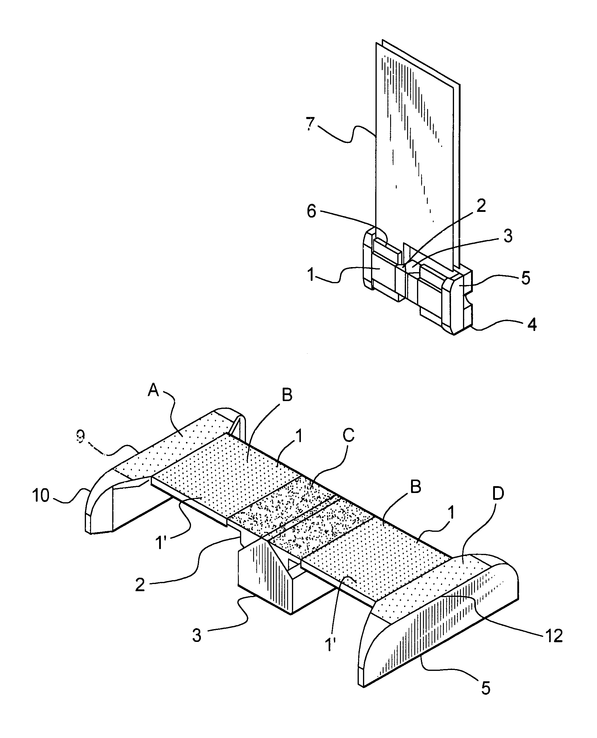
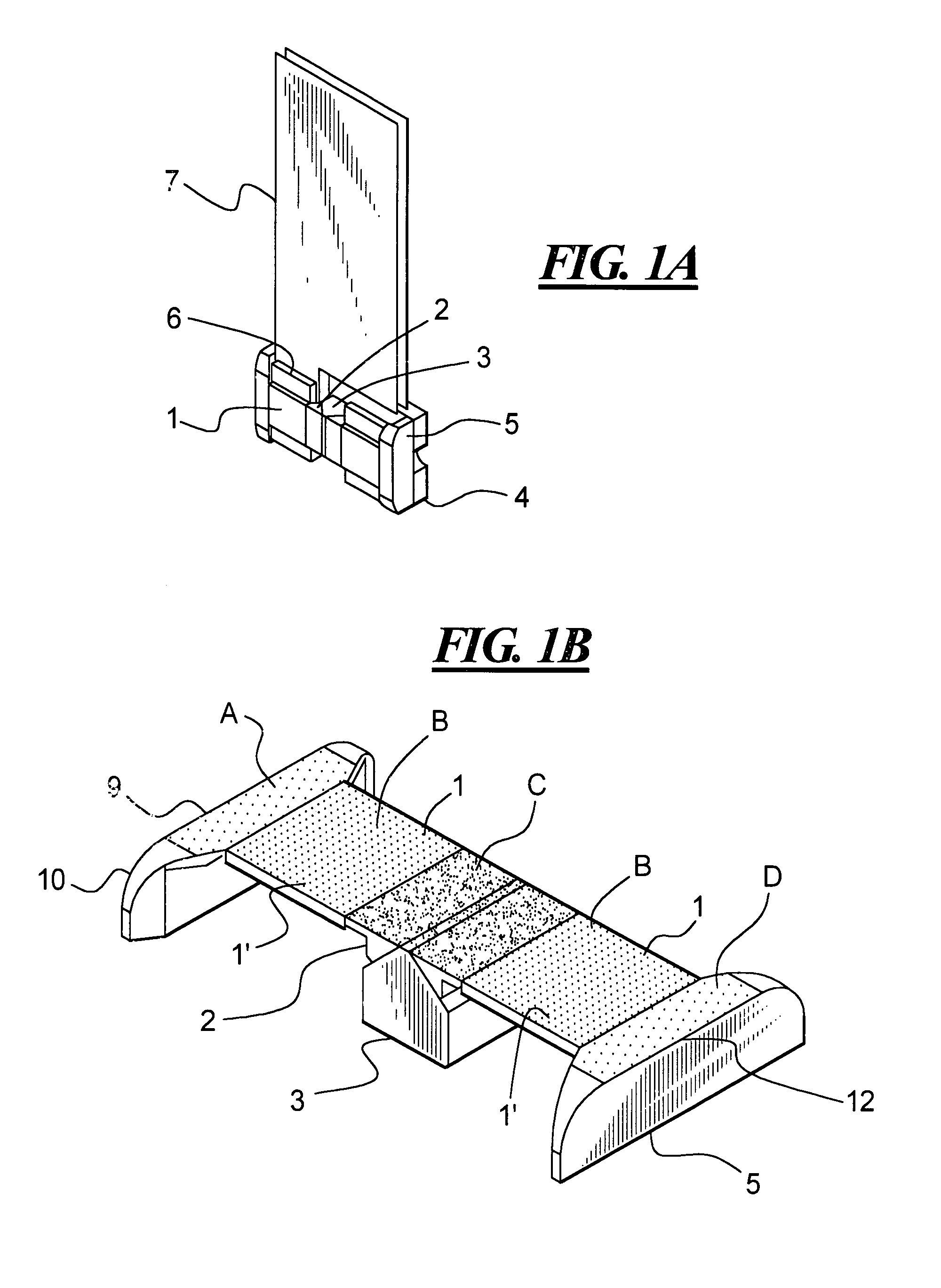
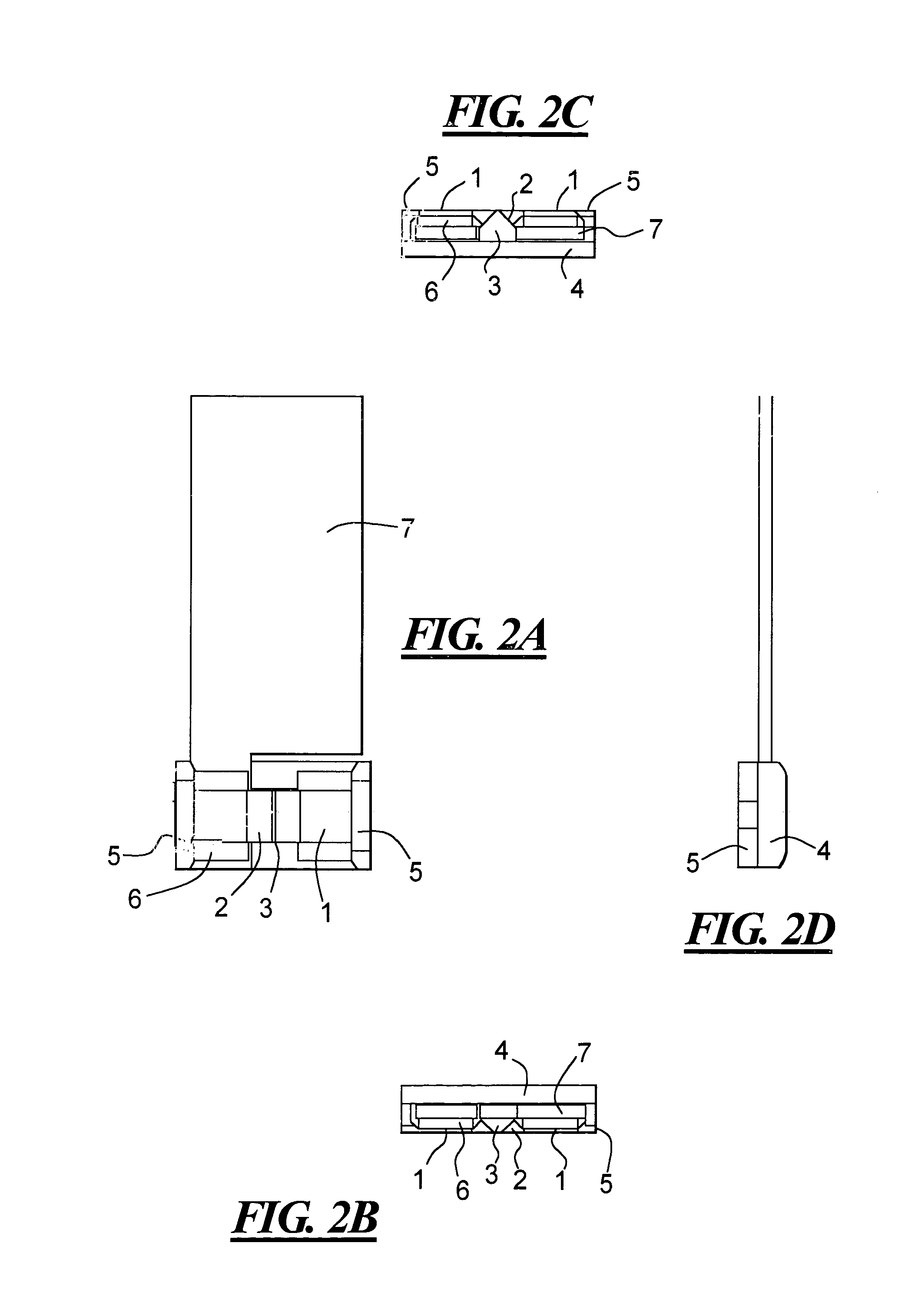
[0007]The present invention builds on the principle that a tape can be pushed down to a flat surface by atmospheric pressure after passing over a relatively sharp edge. A flat contour head is provided with relatively sharp edges in the tape movement direction in order to obtain the necessary head to tape spacing and positional stability.

Problems solved by technology

This is not possible with a matrix head where the head gaps are spread over a flat surface area.

Method used


Image

  • Write/read head assembly with wear parts
  • Write/read head assembly with wear parts
  • Write/read head assembly with wear parts

Examples


second embodiment

[0057]FIG. 6 shows a second embodiment where the wear parts are formed like a pair of “shoes”14 and 15 that completely surround the write chips 1 and the optical part 3. The leading and trailing edges of the wear parts are shown as 9 and 12. Only one flex cable 13 is shown.

[0058]One alternate possibility is to eliminate the part of the shoes 14 and 15 that contains the leading and trailing edges 9 and 12, and have the edge wear function integrated in the write chip (for example by being made at the wafer process level as several layers of wear resistant material).

[0059]FIGS. 7A, 7B, 7C and 7D show a front, top, bottom and side view of the read / write head assembly of the second embodiment. The outer wear parts are formed like “shoes”14 and 15

[0060]FIG. 8 shows the section view along line B—B of FIG. 7A with the portions of the shoes 14 and 15 indicated.

[0061]FIG. 9 is an exploded view of the wear parts 14 and 15 with the respective tape wrap edges 9 and 12, the write chips 1, the sup...

third embodiment

[0062]FIG. 10 shows an embodiment where the write chips 1 are held in wear bars 20 that are mounted to a head frame 17. the read / write head assembly is free to move or rotate relative to a readout prism 19, which is held by wear / support parts 18. The head assembly is mounted on a head platform 16 onto which the readout prism is mounted. Part number 21 is a flex cable directly soldered to the write chip pads. The write chips are mounted to a head frame that can rotate about a center O. This means that the write head azimuth can be adjusted dynamically without influencing the optical read alignment.

[0063]Since the write heads are rotatable relative to the head platform 16, azimuth errors are compensated. It is also possible to move the head in the transverse direction relative to the tape movement to verify written tracks. This movement follows the lateral movement of the written tracks during the read operation.

[0064]FIG. 11 shows the head frame 17 provided with ribs 22 between the w...


PUM

PropertyMeasurementUnit
tape wrap angleaaaaaaaaaa
atmospheric pressureaaaaaaaaaa
flexibleaaaaaaaaaa

Abstract

A read / write head of a magnetic tape drive is provided, where the matrix write head is provided as a part of an overall flat structure that utilizes the atmospheric pressure to hold the tape against the operational surface of the write head. The read head portion is provided to enable reading of the data immediately after it is written. The present head structure permits writing and reading of written data in both tape travel directions. The matrix write head portions are on chips and wear parts are in the upstream direction with respect to the tape travel from the write head. The wear parts provide a shape edge over which the tape moves. The read head is either optical or magnetic and is between two portions of the write head.

Description

BACKGROUND OF THE INVENTION[0001]1. Field of the Invention[0002]The present invention relates generally to a head assembly for reading, reproducing and / or erasing information in a track of a flexible tape media. This invention is in particular directed to a read / write head having an approximately flat head to tape contact surface where the atmospheric pressure creates the necessary head to tape spacing.[0003]2. Description of the Related Art[0004]The trend in data storage is to provide higher capacity, faster access and increased data transfer rates. To obtain an optimum performance in writing to and reading from a flexible tape media, it is necessary that the head is kept in close and stable contact to the tape media surface. A robust system requires a head to tape spacing which is not very sensitive to variations of tape speed or tape tension.[0005]Access time to data can be highly improved (reduced) by utilization of wider and shorter tape media. When using wide tape, the read / wr...

Claims


Application Information

Patent Timeline
Patent Type & Authority Patents(United States)
IPC IPC(8): G11B5/584
CPCG11B5/584
Inventor RUDI, GUTTORMRUBAS, LADISLAVMIYAMOTO, CLIFF
Owner TANDBERG DATA
Learn More