Selective backpressure control for multistage switches

a multi-stage switch and selective backpressure technology, applied in data switching networks, frequency-division multiplexes, instruments, etc., can solve problems such as congestion, congestion, and congestion, and achieve efficient and accurate congestion conditions.

Inactive Publication Date: 2005-12-06
CISCO TECH INC
View PDF6 Cites 127 Cited by
  • Summary
  • Abstract
  • Description
  • Claims
  • Application Information

AI Technical Summary

Benefits of technology

[0015]In an alternate embodiment, the ingress linecard may combine the information in the backpressure signal with the ingress linecard's own (local) queue status. Thus, the ingress linecard can make an even finer-grained determination of congestion control by factoring in its current queue status with the downstream fabric queue status from the switch element(s) and the egress linecard.
[0016]In a further alternate embodiment, queue status calculating mechanisms may be pres

Problems solved by technology

Multi-element switch fabrics typically lack a deterministic scheduling mechanism.
Under certain conditions, congestion may occur due to over-loading of an internal link between switch elements 110.
If this backpressure signal does not distinguish between the various component traffic that is aggr

Method used


Image

  • Selective backpressure control for multistage switches
  • Selective backpressure control for multistage switches
  • Selective backpressure control for multistage switches

Examples


embodiment

Representative Embodiment

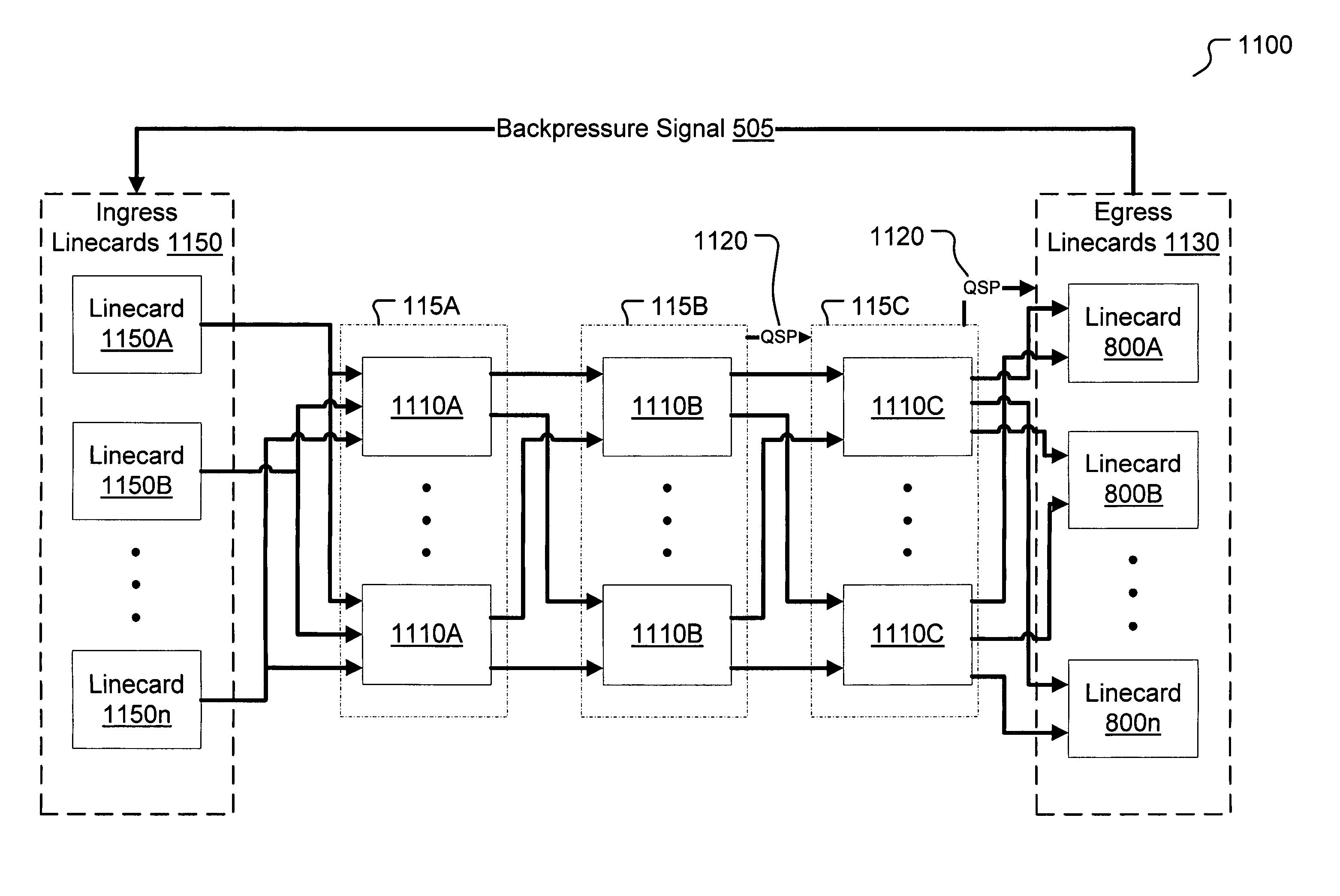
[0035]Ingress linecards 130 (referring back to FIG. 1 momentarily), collectively consist of one or more physical linecards. These linecards, as are well known in the art, consist of one or more ports connected to a network and conventional packet parsing, classification logic, and buffering circuits. Each linecard typically also includes a queuing structure whereby packets are stored or buffered for sequential transmission out of the linecard into the rest of the switching fabric. Such queuing structures are well known in the art and will not be further discussed herein except to note that multiple forms of queuing structures are contemplated in all embodiments of the present invention. Accordingly, the present invention is not limited to any one form of queuing structure.

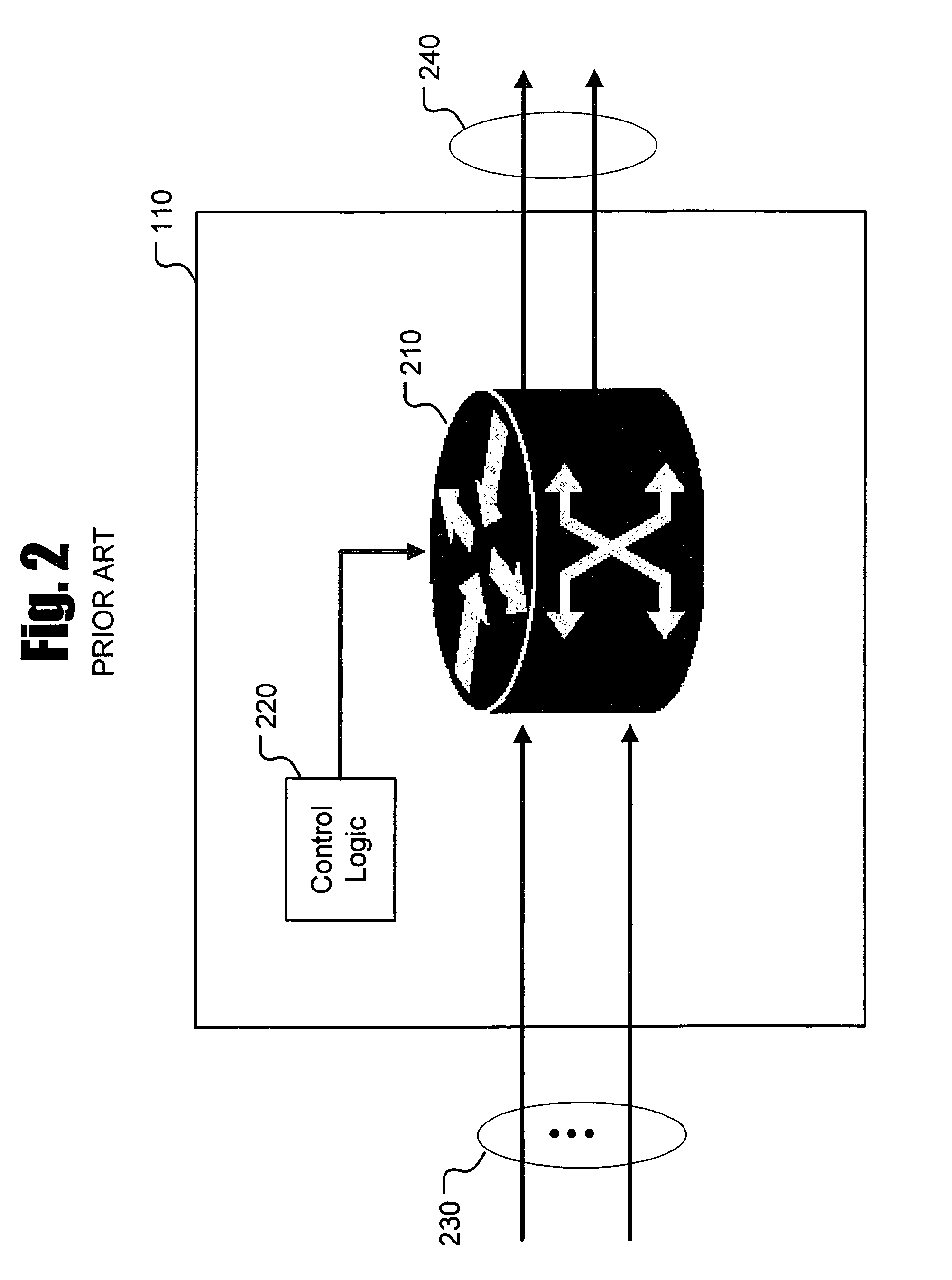
[0036]FIG. 2 shows a switch element 110 of a prior art, multi-stage interconnection network. Prior art switch element 110 consists of conventional packet switching circuits 210 and control ...


PUM


Abstract

A method and apparatus for applying selective backpressure to control a multi-stage interconnection network (MIN). At one or more stages in the MIN, local information is used to define a queue status parameter for each local queue in the fabric. At the egress linecard, the upstream queue status parameter is periodically combined with the egress linecard's output queue status to generate a queue-specific backpressure signal. The backpressure signal continuously indicates to the ingress linecard that a specific fabric queue or queues is experiencing congestion and that the ingress linecard should therefore slow down or stop sending additional packets to the affected queue. Status computation mechanisms, which are state machines in one embodiment of the present invention, are incorporated in each switch element in at least the last stage of the switch fabric. In an alternate embodiment, the ingress linecard further combines the backpressure signal with its own local queue status to influence the initial queuing decision. In another alternate embodiment, queue status calculating mechanisms are present within one or more stages further upstream from the last stage of the switch fabric. Queue status information from many stages can thus be scaleably combined with egress queue status to determine fabric congestion conditions efficiently and accurately in all queues.

Description

BACKGROUND OF THE INVENTION[0001]1. Field of the Invention[0002]The present invention relates to computer network communication devices, in particular multi-element switches.[0003]2. Description of the Related Art[0004]Multi-element switching (or “switch”) fabrics, also known as multistage interconnection networks (MINs) are well known in the art. See, for example, Jonathan Turner and Naoki Yamanaka, “Architecture Choices in Large Scale ATM Switches,” IEICE Transactions 1998 (using the term “Buffered Multistage Switches” rather than the more common “MIN”), incorporated herein by reference in its entirety. MINs connect a set of independent ingress linecards (which receive data packets into the switch) to a set of egress linecards (which send switched packets out of the switch). The ingress and egress linecard functions may be implemented on the same physical circuit board or on two separate boards. Both types of linecard boards are well known in the art.[0005]Referring to FIG. 1, the...

Claims


Application Information

Patent Timeline
IPC IPC(8): H04L12/56
CPCH04L45/00H04L47/263H04L47/30
Inventor CASLEY, ROSS T.LEVY, JOHN B.
Owner CISCO TECH INC
Why Eureka
Try Eureka