Lane keep control apparatus and method for automotive vehicle

a technology for keeping control apparatus and automobile vehicles, applied in the direction of vehicle safety arrangements, process and machine control, braking components, etc., can solve the problem of giving an unpleasant feeling to the driver, and achieve the effect of reducing the deviation in the driving feeling of the driver

Inactive Publication Date: 2005-12-06
NISSAN MOTOR CO LTD +1
View PDF19 Cites 40 Cited by
  • Summary
  • Abstract
  • Description
  • Claims
  • Application Information

AI Technical Summary

Benefits of technology

[0007]It is, hence, an object of the present invention to provide lane keep control apparatus and method for an automotive vehicle whi

Problems solved by technology

Hence, in this case, if the control is suspended, a deviation from a driver's drive feeling occurs so

Method used


Image

  • Lane keep control apparatus and method for automotive vehicle
  • Lane keep control apparatus and method for automotive vehicle
  • Lane keep control apparatus and method for automotive vehicle

Examples


first embodiment

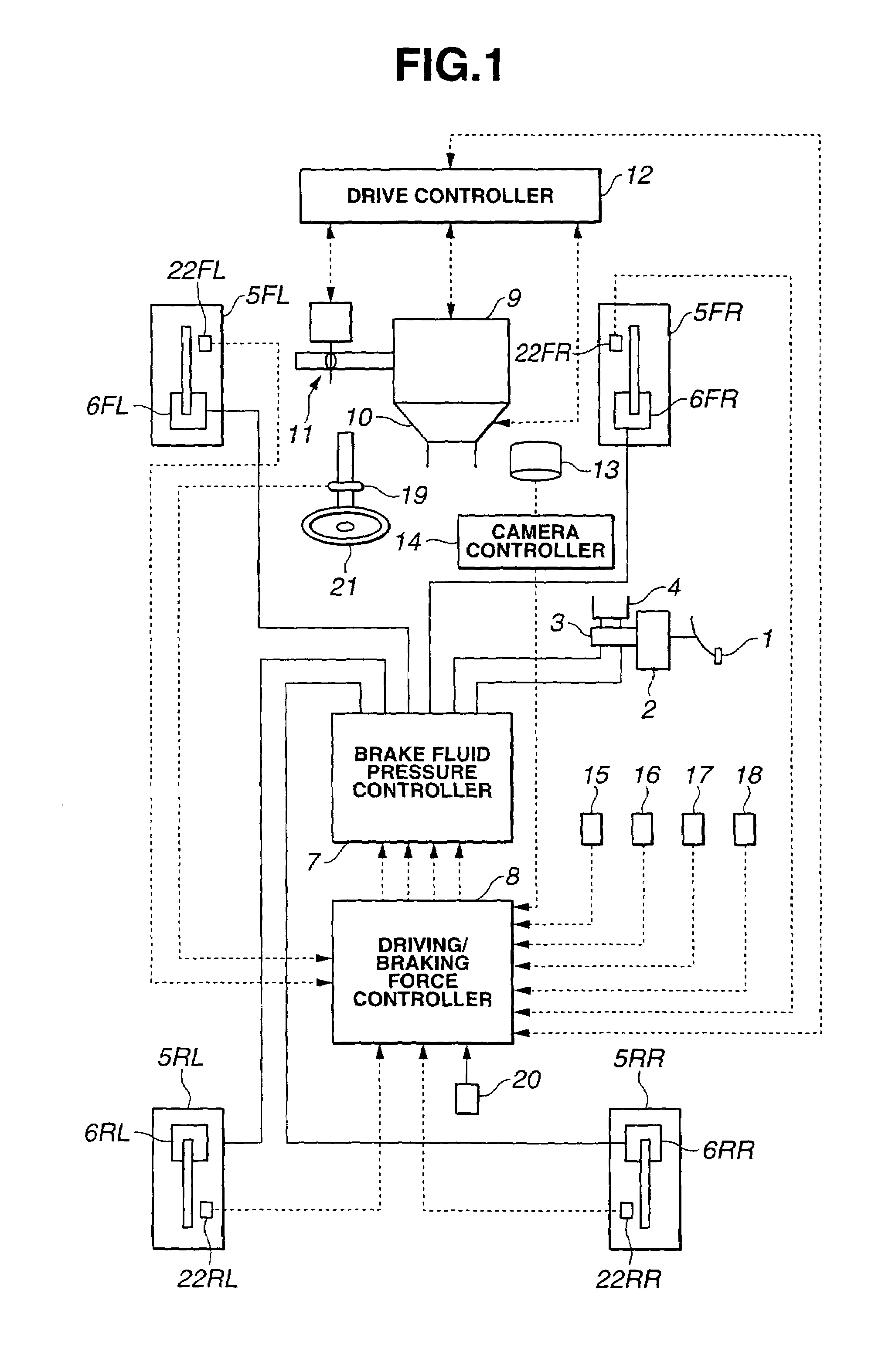
[0022]FIG. 1 shows a rough configuration view of an automotive vehicle to which a lane keep control apparatus in a first preferred embodiment according to the present invention is applicable. The vehicle used in the first embodiment is a rear-wheel driven vehicle in which an automatic transmission and a conventional differential gear are mounted and a vehicular brake system is mounted so as to be enabled to control braking forces applied to front left and rear left road wheels independently of each other and front right and rear right road wheels independently of each other. In FIG. 1, in the brake system of the vehicle (host vehicle), a brake pedal 1 is mounted, a brake force (booster) 2 is mounted, a master cylinder 3 is mounted, and a reservoir 4 is mounted. Usually, in accordance with a depression depth of brake pedal 1 by the vehicle driver, a brake fluid pressure boosted by means of a master cylinder 3 is supplied to each wheel cylinder 6FL through 6RR of corresponding one of ...

second embodiment

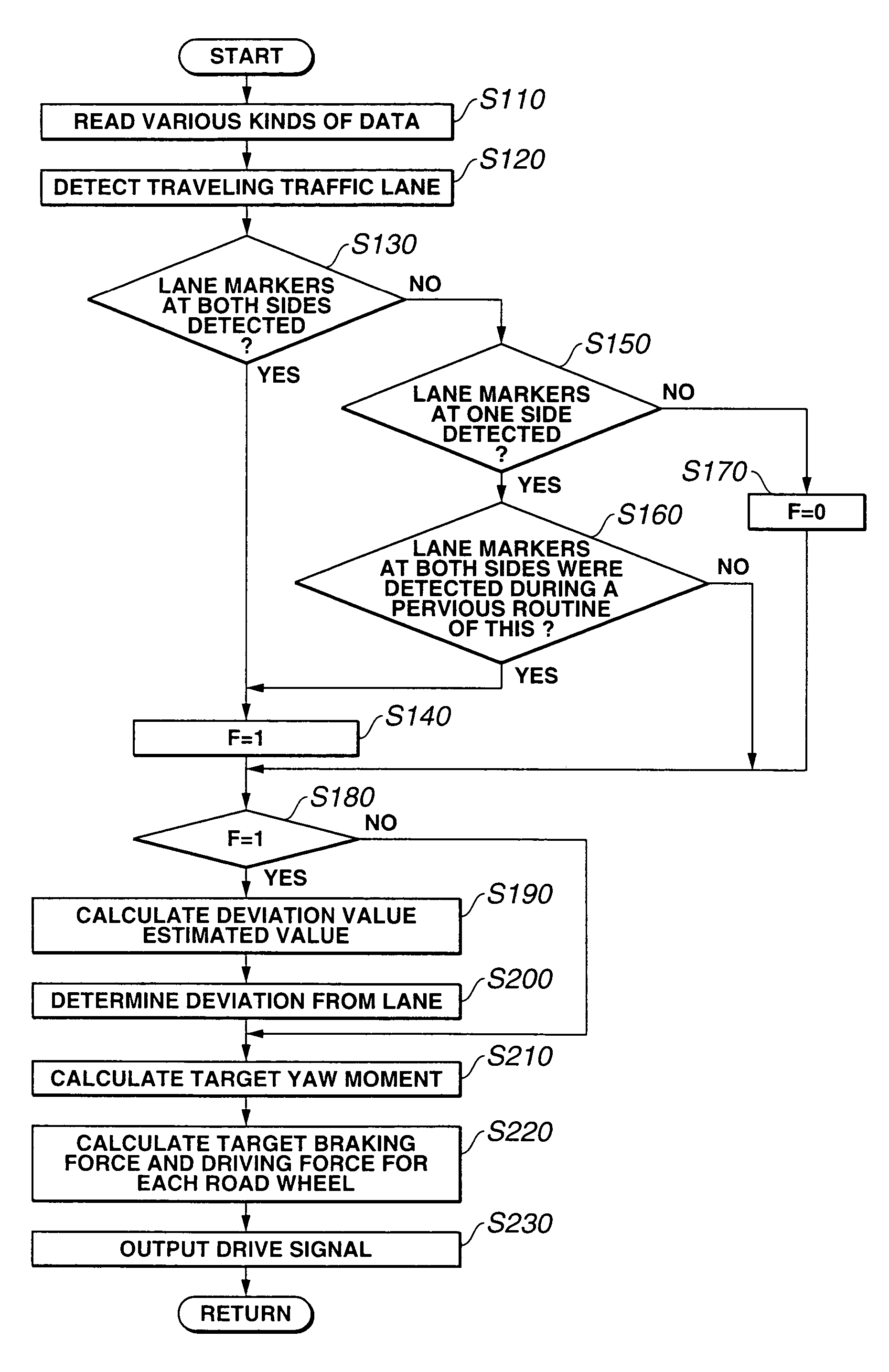
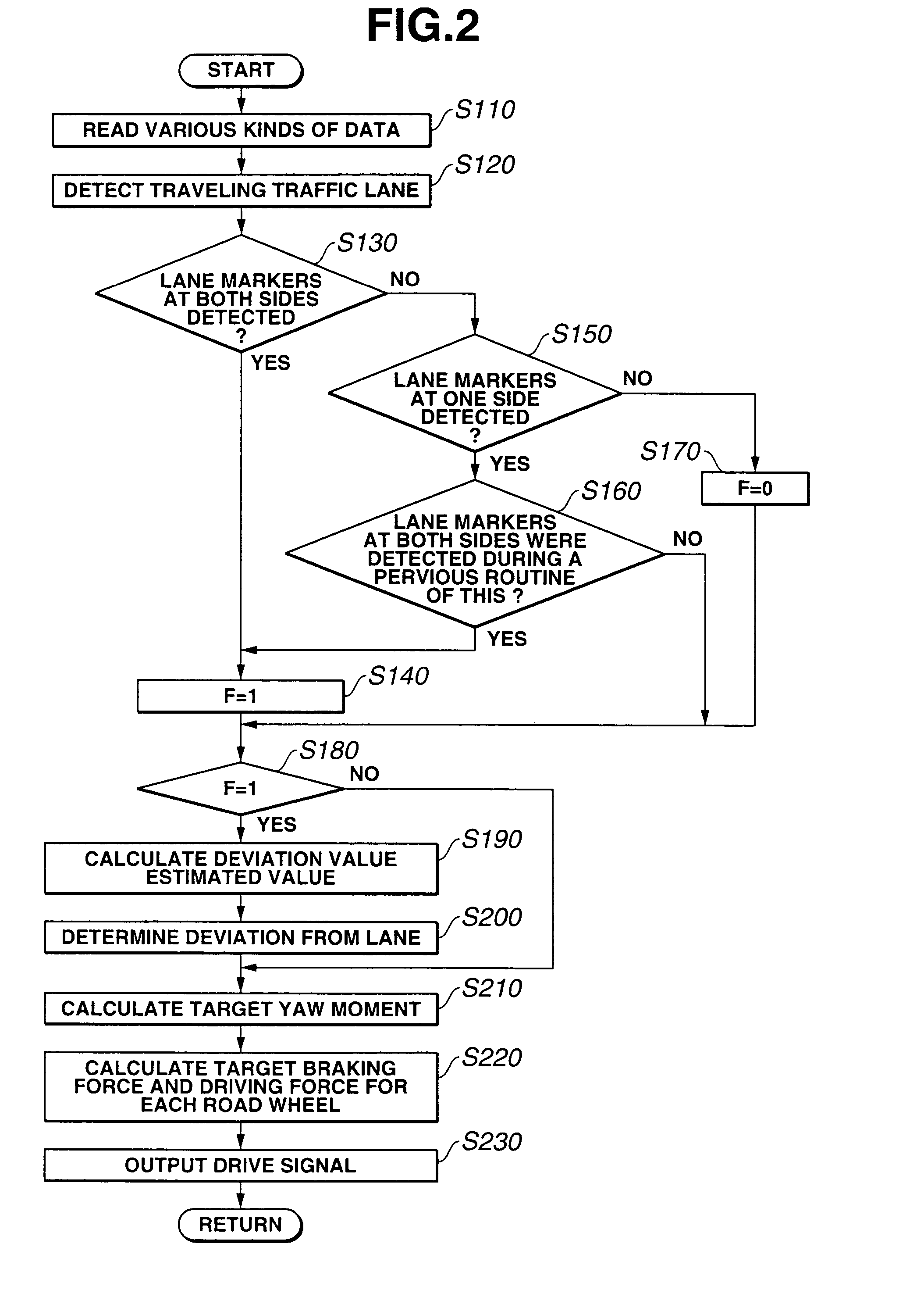
[0044]As described above, in the second embodiment, each sensor shown in FIG. 1, camera controller 14 and steps S110 and S120 shown in FIG. 7 constitute traveling state detecting means (section), step S120 shown in FIG. 7 constitutes traffic lane and lane marker detecting means (section), step S131 in FIG. 7 and step S161 constitute lane marker certainty detecting means (section), step S190 and step S200 shown in FIG. 7 constitutes deviation determining means (section), steps S210 through S230, the brake fluid pressure control circuit 7 and drive (torque) controller 12 constitutes vehicular behavior controlling means (section). Step S130 shown in FIG. 7, brake fluid pressure control circuit 7 shown in FIG. 1, and drive (torque) controller 12 constitute braking / driving force controlling means (section).

[0045]Next, a third preferred embodiment of the traffic lane keep control apparatus according to the present invention will be described below.

[0046]The rough configuration of the vehi...


PUM


Abstract

In lane keep control apparatus and method for an automotive vehicle, a behavior of the vehicle is controlled in such a manner that a yaw moment is developed in a direction to avoid a deviation of the vehicle from the traffic lane in accordance with the traveling state of the vehicle when determining that the vehicle has a tendency of the deviation of the vehicle from the traffic lane and lane markers are detected, each lane marker representing one side of the traffic lane, and the behavior of the vehicle is controlled on the basis of the detected lane marker at one side of the traffic lane when a detection state of the lane markers is transferred from a state in which both of the lane markers at both sides of the traffic lane are detected to a state in which the lane marker only at one side of the traffic lane is detected.

Description

BACKGROUND OF THE INVENTION[0001]1. Field of the Invention[0002]The present invention relates to lane keep control apparatus and method for an automotive vehicle to prevent a deviation of the vehicle in which the lane keep control apparatus is mounted (also called, a host vehicle) from a traffic lane on which the vehicle is traveling when the host vehicle is about to be deviated from the traffic lane during the travel of the vehicle.[0003]2. Description of the Related Art[0004]A Japanese Patent Application First Publication No. Heisei 11-96497 published on Apr. 9, 1999 exemplifies a first previously proposed lane keep control apparatus in which, for example, a controller determines that the host vehicle is about to be deviated from the traffic lane and outputs a steering torque to a degree such that a vehicular driver's force easily overcomes via a steering actuator in accordance with a lateral deviation quantity (variable) of the host vehicle with respect to a reference position of...

Claims


Application Information

Patent Timeline
IPC IPC(8): B60R21/00B60K31/00B60T7/12B60T8/17B60T8/1755G05D1/02G08G1/16
CPCB60K31/0066B60T7/12B60T8/1755B62D15/025G05D1/0246B60T2201/08B60T2201/083B60T2260/09B60W2520/14G05D2201/0213
Inventor TANGE, SATOSHIMATSUMOTO, SHINJI
Owner NISSAN MOTOR CO LTD
Why Eureka
Try Eureka