
Method for allocating network aggregation bandwidth and a network system using the same

a network system and network aggregation technology, applied in data switching networks, instruments, high-level techniques, etc., can solve the problems of increasing the required bandwidth resources and apparent inefficiency

Inactive Publication Date: 2005-12-06
FUJITSU LTD
View PDF8 Cites 55 Cited by
  • Summary
  • Abstract
  • Description
  • Claims
  • Application Information

AI Technical Summary

Benefits of technology

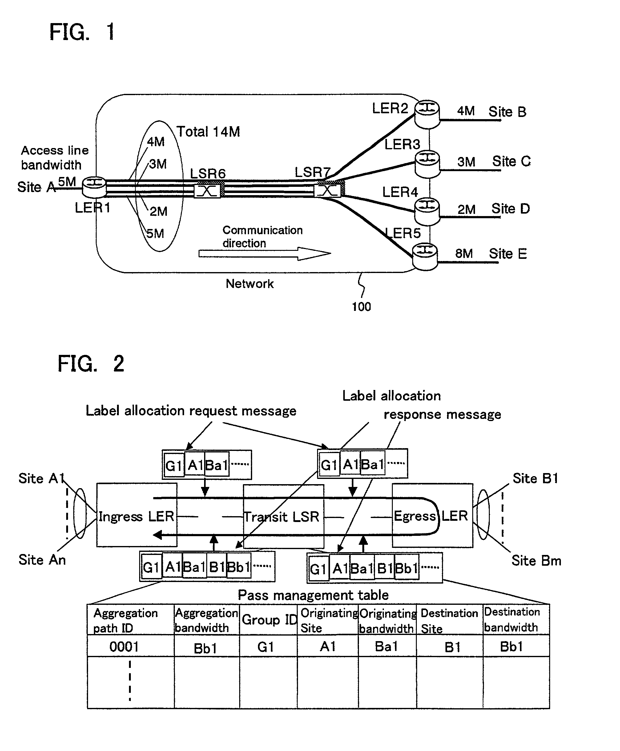
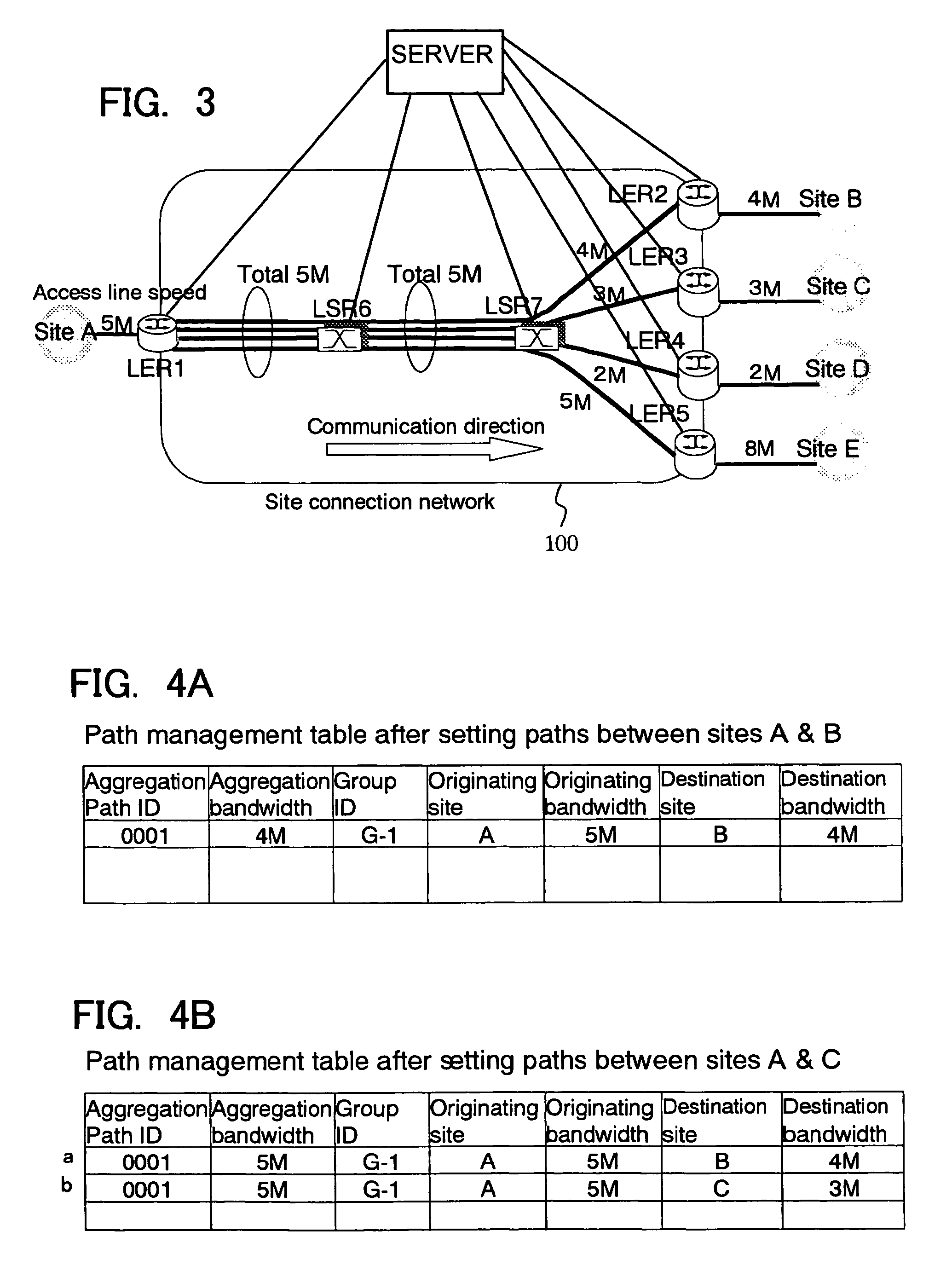
The present invention provides a method and network system for calculating and controlling network bandwidth in a packet-based VPN (virtual private network) using a protocol such as IP and MPLS for interconnecting communication sites. The method and system allow for a more efficient allocation of network bandwidth among multiple paths, based on factors such as link speed, gateway capability, and server capability. This helps to avoid the conventional problem of increased network bandwidth requirements as the squared number of sites increases. Additionally, the method and system allow for the dynamic allocation of network bandwidth based on changes in access line bandwidth or the interrelation of bandwidth sizes between destination and originating sites. The server in the network system calculates the aggregation path and bandwidth allocation, and transmits the information to each transit node for transmission in forward or backward direction. The technical effects of the invention include improved network bandwidth utilization and more efficient network interconnection.

Problems solved by technology

This is apparently inefficient because required bandwidth resources increase with the squared number of sites.

Method used


Image

  • Method for allocating network aggregation bandwidth and a network system using the same
  • Method for allocating network aggregation bandwidth and a network system using the same
  • Method for allocating network aggregation bandwidth and a network system using the same

Examples


second embodiment

[A Second Embodiment]

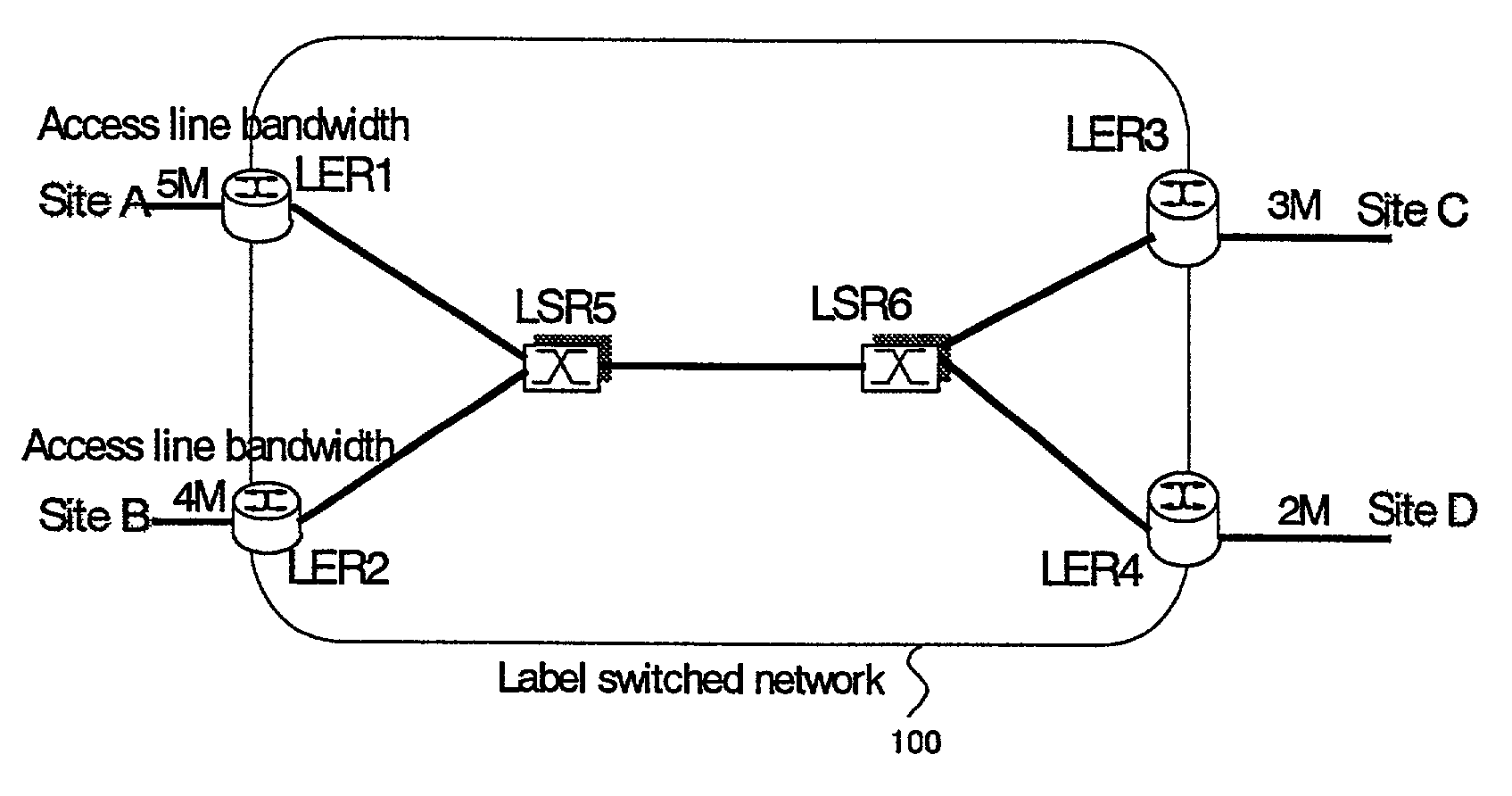
[0106]In FIG. 8, there is shown an example of a network configuration for illustrating a second embodiment of the present invention. In this case, a plurality of originating sites as well as a plurality of destination sites exist. The operation is as follows.

[0107]In FIG. 8, user sites A, B, C and D are provided with access lines having an upper limit speed of 5 Mbps, 4 Mbps, 3 Mbps and 2 Mbps. Each site is connected to a MPLS label switched network 100.

[0108]Site A is connected to LER1 (LER: label edge router) which is an edge node in a label switched network 100 with an access line bandwidth of 5 Mbps. As for site B to D, the situations are similar to the above-mentioned site A.

[0109]In FIG. 8, label switched network 100 is constituted by LER1 to LER4 locating at the edges, and LSR5 and LSR6 (LSR: label switch router) forming a core of the network. It is assumed that LDP (label distribution protocol) is used as a protocol for establishing an MPLS path (referre...


PUM


Abstract

A method and a system using the method enabling to decrease required resource for the bandwidth reservation in an inter-site connection network used for communication between communication sites. The aggregation of bandwidth is considered for allocating bandwidth in the inter-site connection network. The network consists of a plurality of nodes each having a packet switch, and a plurality of user sites each constituted by a host or an internal network respectively connected to the plurality of nodes via access lines. With respect to the plurality of user sites, when one user site is to be connected to the other site through the network, a necessary and sufficient bandwidth for interconnecting between the user site and the other is calculated according to the bandwidth of the access line connecting the user site to the network considered as a minimal bandwidth. Based on the calculated result, the bandwidth is allocated to the plurality of nodes.

Description

FIELD OF THE INVENTION[0001]The present invention relates to a method for allocating shared bandwidth in a packet switch using IP (Internet protocol), MPLS (multi protocol label switching) or the like, and a network system using the method.BACKGROUND OF THE INVENTION[0002]In an MPLS network or an IP network consisting of an ingress node, an egress node and a transit node interconnected by links, a bandwidth reservation function is adopted using RSVP (resource reservation protocol).[0003]In such a network, when a bandwidth is to be reserved on a communication route from an ingress point to an egress point, the same bandwidth is reserved on a link by link basis using a bandwidth reservation protocol. Such a communication route on which a bandwidth is reserved is hereafter referred to as a “path”.[0004]In the conventional method, a bandwidth is determined during path establishment procedure. A bandwidth reservation protocol is used for transmitting a message containing a requested band...

Claims


Application Information

Patent Timeline
Patent Type & Authority Patents(United States)
IPC IPC(8): H04L45/125H04L47/41
CPCH04L12/5695H04L41/0896H04L45/245H04L45/50H04L47/724H04L47/822H04L47/825Y02B60/33H04L47/70Y02D30/50
Inventor NOMURA, YUJI
Owner FUJITSU LTD
Learn More