Layered heat exchanger, layered evaporator for motor vehicle air conditioners and refrigeration system

a technology for evaporators and motor vehicles, which is applied in indirect heat exchangers, lighting and heating apparatuses, laminated elements, etc. it can solve the problems of insufficient cooling efficiency, insufficient overall efficiency of refrigeration systems, and failure to fully uniformly divide fluids or achieve uniform division of fluids, etc., to achieve a higher diffusing effect and increase design freedom

Inactive Publication Date: 2005-12-13
SHOWA DENKO KK
View PDF13 Cites 19 Cited by
  • Summary
  • Abstract
  • Description
  • Claims
  • Application Information

AI Technical Summary

Benefits of technology

[0012]With the layered heat exchanger of the present invention, the division of the fluid from the upper header into the flat tubes is adjusted by the fluid diffusing portion, with the result that uniformly divided flows of fluid are available to achieve a greatly increased heat exchange efficiency.
[0028]The through hole covered with the fluid diffusing portion may be circular, with the fluid diffusing portion in the form of an annular portion covering a peripheral portion of the hole. The through hole may then have a central portion in the form of a nozzle. It is then possible to adjust the outflow of the fluid from the central portion and the fluid outflow from the peripheral portion individually. This leads to increased freedom of design and a higher diffusing effect.

Problems solved by technology

However, this method encounters the problem of failing to divide the fluid fully uniformly or attaining uniform division of the fluid at the sacrifice of channel resistance to the fluid.
For this reason, the problem of an insufficient cooling efficiency arises when such a layered heat exchanger is used as the evaporator for motor vehicle air conditioners.
Further in the case where such a layered heat exchanger is used as the evaporator to provide a refrigeration system which comprises a compressor for compressing a refrigerant, a condenser for condensing the compressed refrigerant, a pressure reducing device for passing the condensed refrigerant therethrough for a pressure reduction, and an evaporator for evaporating the refrigerant from the device to return the resulting refrigerant to the compressor, the refrigeration system has the problem of being insufficient in overall efficiency since the evaporator is insufficient in the function of diffusing the refrigerant therethrough.

Method used


Image

  • Layered heat exchanger, layered evaporator for motor vehicle air conditioners and refrigeration system
  • Layered heat exchanger, layered evaporator for motor vehicle air conditioners and refrigeration system
  • Layered heat exchanger, layered evaporator for motor vehicle air conditioners and refrigeration system

Examples


Embodiment Construction

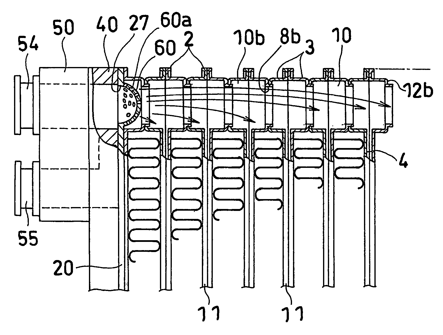
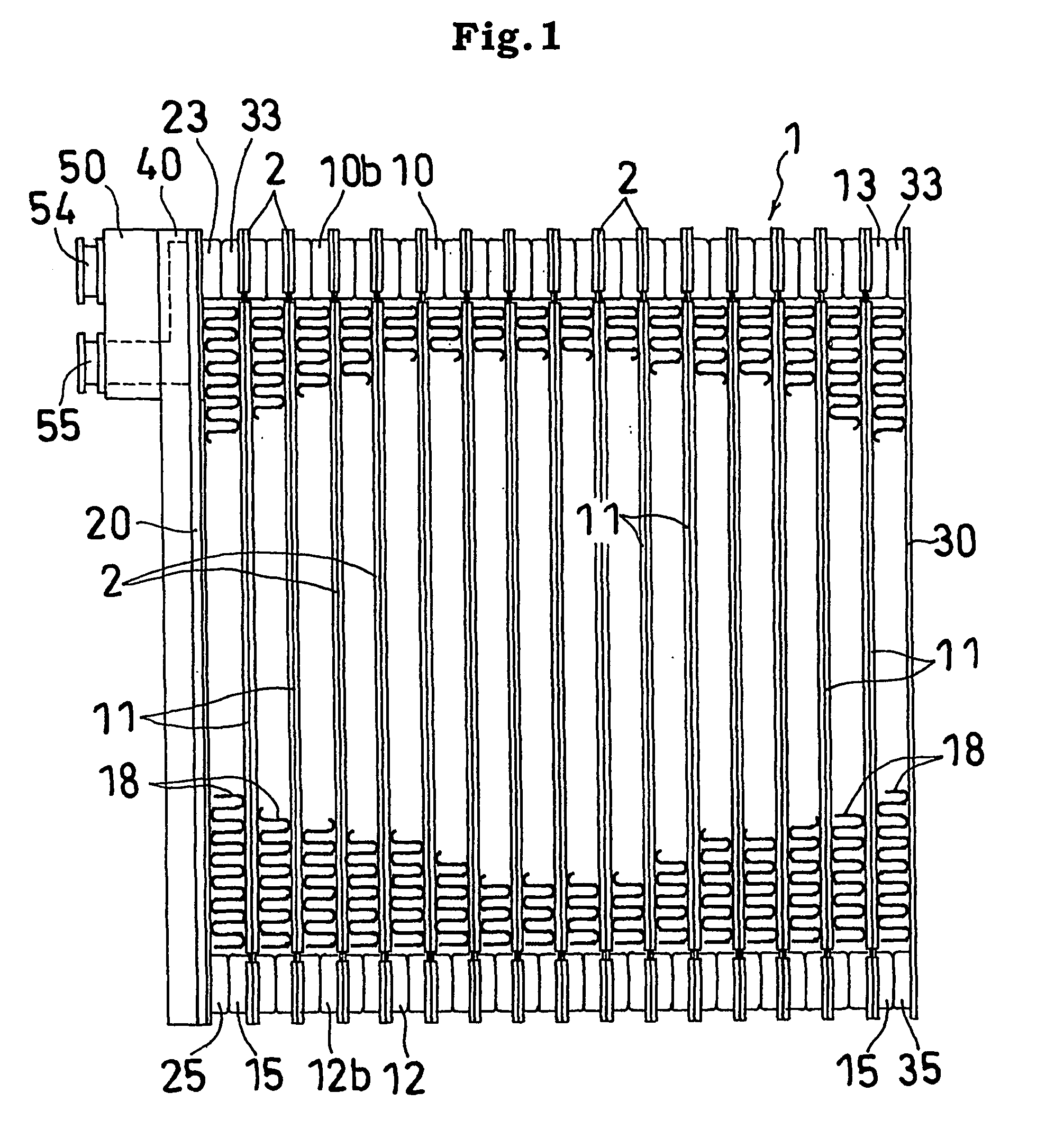
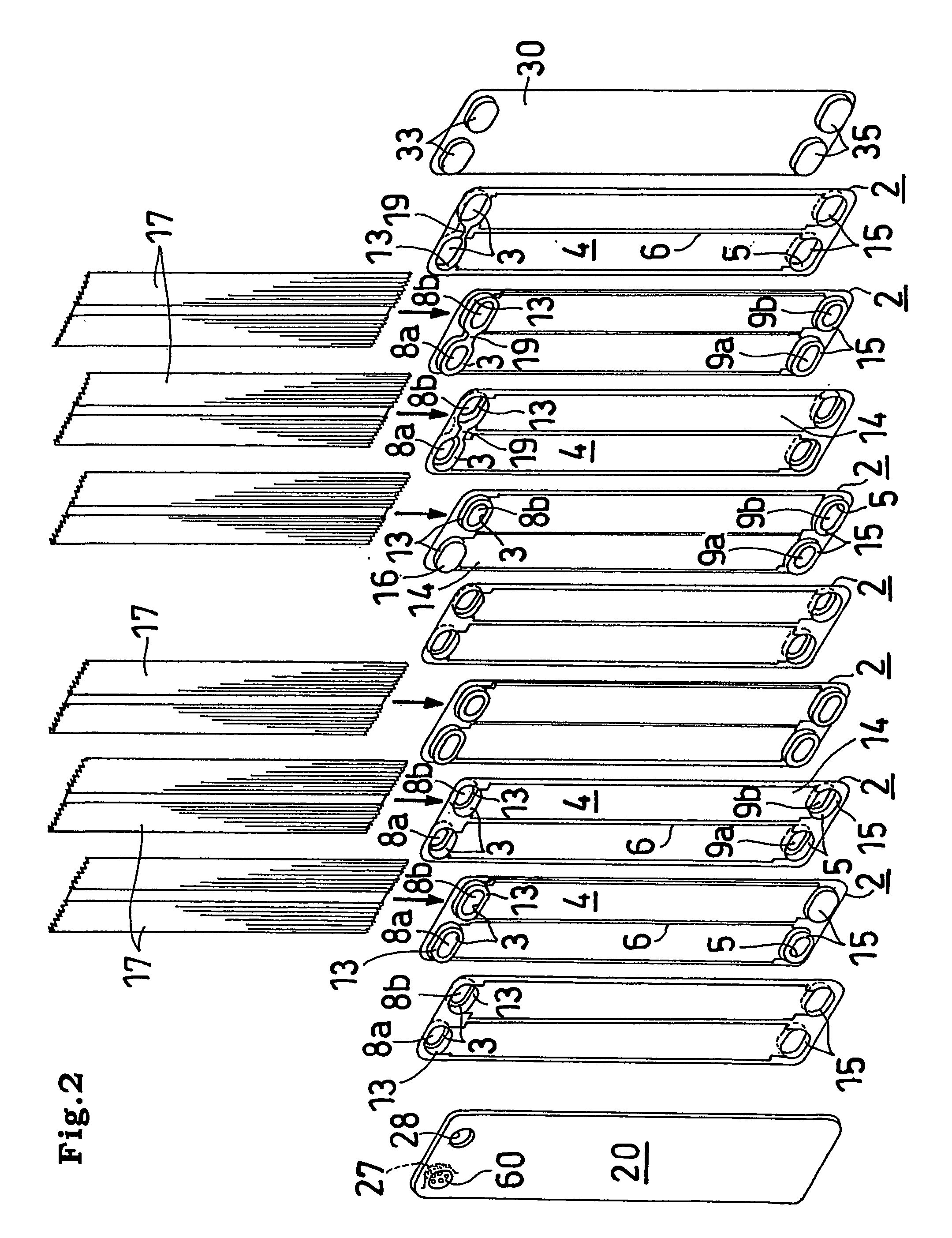
[0038]With reference to FIGS. 1 to 4, embodiments of layered heat exchanger of the invention will be described next. The drawings show the present invention as applied to layered evaporators for use in motor vehicle air conditioners.

[0039]The layered evaporator 1 is made from aluminum (including an aluminum alloy) and comprises a multiplicity of intermediate plate 2 arranged side by side and end plates 20, 30 which are arranged at the left and right sides of the arrangement externally thereof. The evaporator 1 is generally rectangular when seen from the front.

[0040]Each of the intermediate plates 2 has on one side thereof a pair of front and rear cuplike projections 13, 15 formed at the upper and lower ends thereof and having header recesses 3, 5 inside thereof respectively. The plate 2 is provided at an intermediate portion of the height ther of with a bulging portions 14 having inside thereof a tube recess 4 continuous with the header recesses 3, 5. The tube recess 4 is divided in...


PUM


Abstract

An end plate (20) has a fluid inlet hole (27) communicating with a front header (12b) and covered with a fluid diffusing portion (60) which is in the form of a semispherical plate and which has small holes (60a).

Description

CROSS REFERENCE TO RELATED APPLICATIONS[0001]This application is an application filed under 35 U.S.C. §111(a) claiming the benefit pursuant to 35 U.S.C. §119(e)(1) of the filing data of Provisional Application No. 60 / 302,689 filed Jul. 5, 2001 pursuant to 35 U.S.C. §111(b).TECHNICAL FIELD[0002]The present invention relates to layered heat exchangers, layered evaporators for motor vehicle air conditioners and refrigeration systems.[0003]The terms “upper,”“lower,”“left” and “right” as used herein refer respectively to the upper and lower sides, and left- and right-hand sides of FIG. 1, the term “front” refers to the front side of the plane of the same drawing, and the term “rear” to the rear side thereof. However, the terms front, rear, left and right are used for convenience sake, and may be used in reverse relation to the above. Further the fluid inlet and outlet can be used as reversed.BACKGROUND ART[0004]The conventional layered heat exchangers for use as layered evaporators for m...

Claims


Application Information

Patent Timeline
Patent Type & Authority Patents(United States)
IPC IPC(8): F25B39/02F28D1/03F28F27/02
CPCF25B39/022F25B39/028F28D1/0333F28F9/028F28D2021/0085F28F3/08
Inventor HIGASHIYAMA, NAOHISA
Owner SHOWA DENKO KK
Why Eureka
Try Eureka