
Method of measuring flow rate of flowable material under continuous flow conditions, and an in-line continuous flow meter

Inactive Publication Date: 2005-12-13
IOWA STATE UNIV RES FOUND
View PDF16 Cites 23 Cited by
  • Summary
  • Abstract
  • Description
  • Claims
  • Application Information

AI Technical Summary

Problems solved by technology

However, no seed meter is available that meets the criteria of minimum damage to seeds, accuracy of measurement, cost effectiveness, and the feasibility of physical installation for retrofitting the flow meter in existing operations.
Existing devices have limitations in many areas, e.g., they draw a sample from the flow and measure the flow rate according to the weight per unit of time; or they employ a moving mechanism (belt or auger) to move the product and weigh the moving device with the product loaded thereon.
Similar problems arise if the flowable material is a liquid.

Method used


Image

  • Method of measuring flow rate of flowable material under continuous flow conditions, and an in-line continuous flow meter
  • Method of measuring flow rate of flowable material under continuous flow conditions, and an in-line continuous flow meter
  • Method of measuring flow rate of flowable material under continuous flow conditions, and an in-line continuous flow meter

Examples


Embodiment Construction

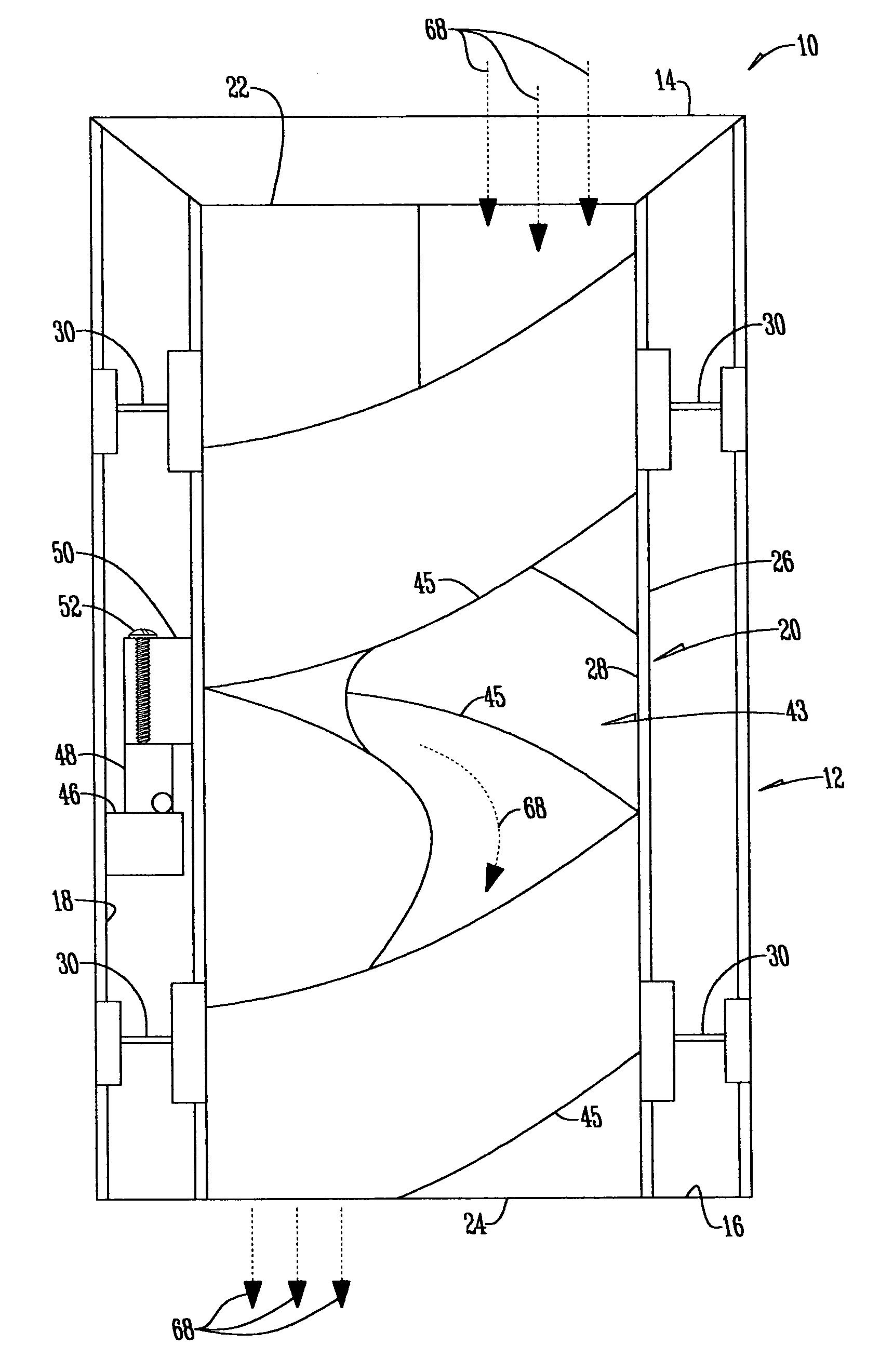
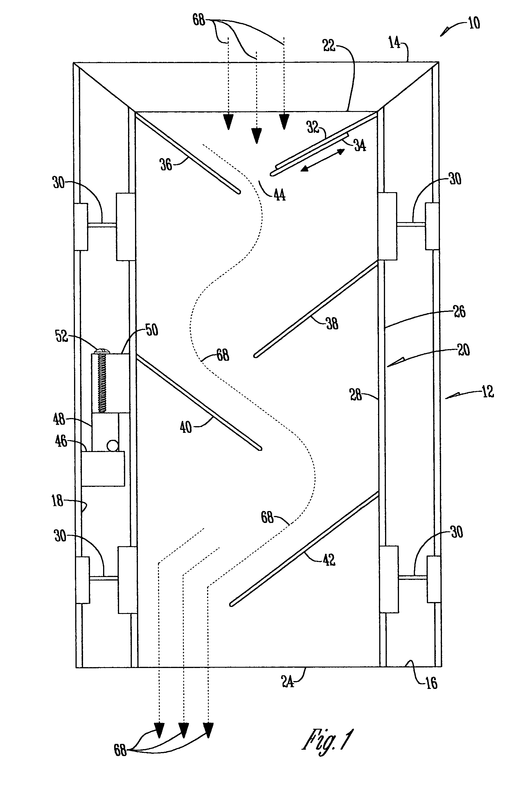
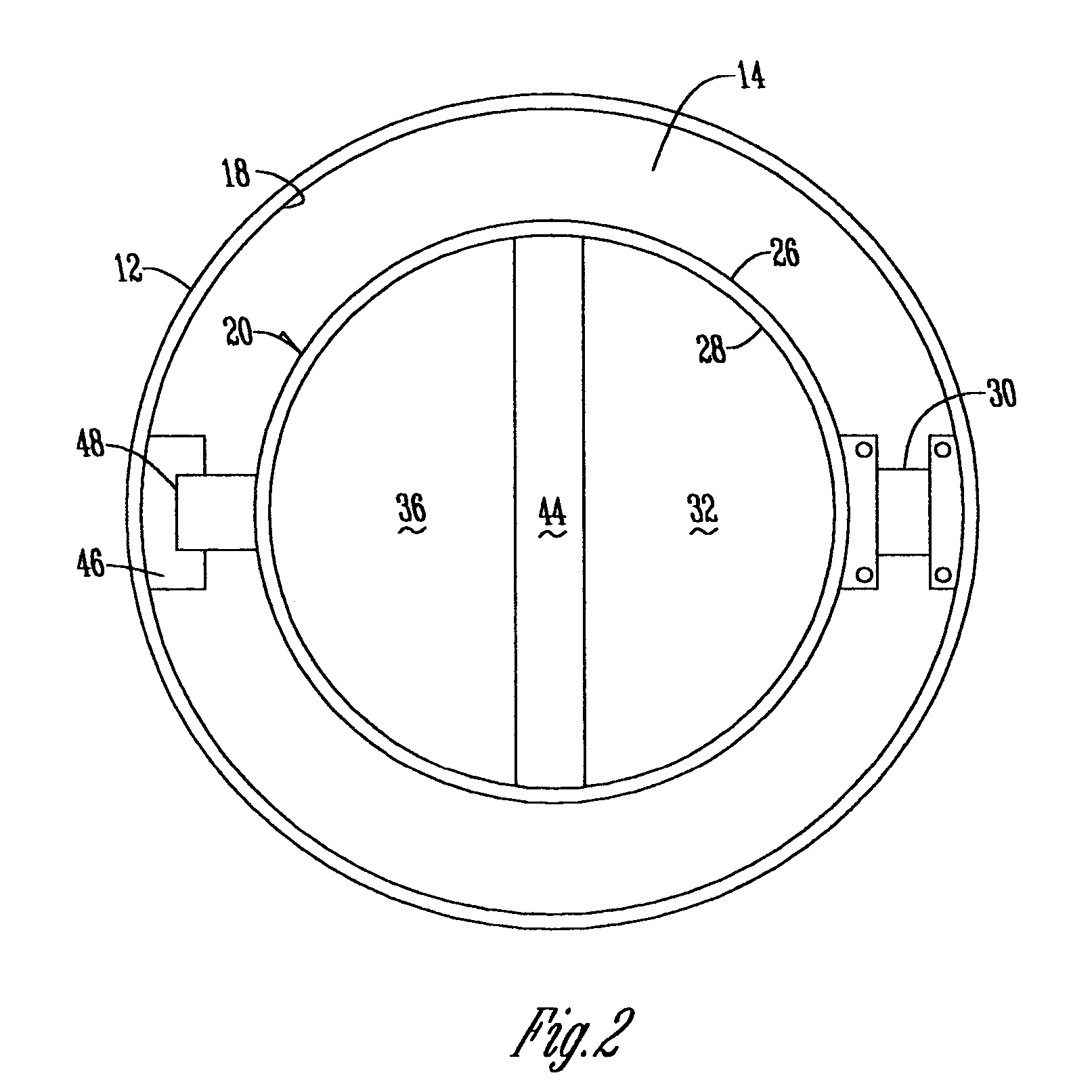
[0014]The description of the invention hereafter will refer primarily to particulate material. It should be understood that this invention is applicable to flowable material whether it be particulate material or liquid material. As such, statements made in regard to particulate material will be equally applicable to liquid material. With reference to FIG. 1, a flow meter 10 includes an outer cylinder or housing 12 which has a top 14, a bottom 16, on an inner surface 18. An inner cylinder or housing 20 is located within housing 12 in spaced relation thereto, and has a top 22, a bottom 24, an outer surface 26 and an inner surface 28. The inner housing 20 is resiliently suspended with housing 12 by leaf spring assemblies 30 which extend between the inner surface 18 of housing 12 and the outer surface 26 of housing 20.

[0015]A diagonal semi-circular plate 32 extends downwardly and inwardly into inner housing 20 from its upper end and has a lower edge that terminates short of the vertical...


PUM


Abstract

A method of determining the rate of flow of a flowable material, particulate or liquid, through a flowable material passageway, comprising causing the material passing through the passageway to move downwardly by gravity slowing the downward movement of material as compared to free falling gravitational movement measuring the weight of material passing slowly downwardly with respect to the passageway; causing an electronic signal to be generated in response to the magnitude of the weight measuring; and connecting the electronic signal to a read out display to reflect the flow rate of material with respect to units of weight with respect to units of time.

Description

CROSS REFERENCE TO A RELATED APPLICATION[0001]This application is a continuation-in-part of application Ser. No. 10 / 336,256 filed Jan. 3, 2003, which claims the benefit of Provisional Patent Application Ser. No. 60 / 346,588 filed Jan. 8, 2002.BACKGROUND OF THE INVENTION[0002]Monitoring and managing material flow through a passageway at different check points in the passageway in real time for conditioning of seeds, for example, can increase operating efficiency and can improve profitability. However, no seed meter is available that meets the criteria of minimum damage to seeds, accuracy of measurement, cost effectiveness, and the feasibility of physical installation for retrofitting the flow meter in existing operations.[0003]Existing devices have limitations in many areas, e.g., they draw a sample from the flow and measure the flow rate according to the weight per unit of time; or they employ a moving mechanism (belt or auger) to move the product and weigh the moving device with the...

Claims


Application Information

Patent Timeline
IPC IPC(8): A23P1/00G01F1/30G01F1/76G01G11/08
CPCG01F1/30G01F1/76G01G11/08
Inventor SHYY, YUH-YUANMISRA, MANJIT K.
Owner IOWA STATE UNIV RES FOUND
Learn More