
Hand tool adjuster

a technology of hand tools and adjusters, which is applied in the direction of rotary couplings, mechanical devices, couplings, etc., can solve the problems of compromising the strength of the tool handle, and tools with mechanical components may not allow precise adjustment or maintenance, etc., to achieve and maintain high torque forces quickly and efficiently, reduce difficulties and disadvantages, and reduce the effect of difficulty and disadvantages

Inactive Publication Date: 2005-12-13
EXPEDITION TOOLS
View PDF17 Cites 13 Cited by
  • Summary
  • Abstract
  • Description
  • Claims
  • Application Information

AI Technical Summary

Benefits of technology

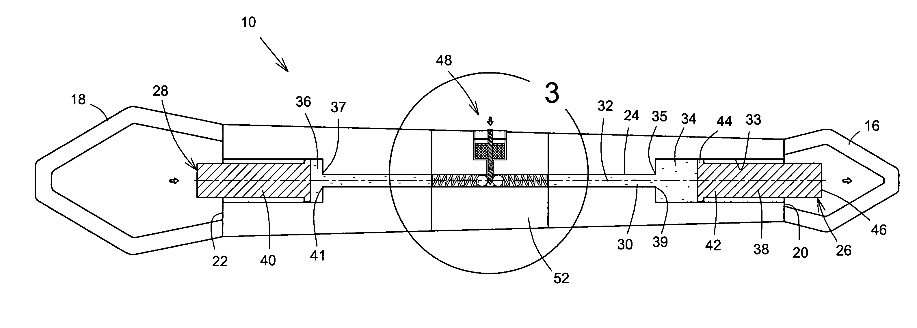
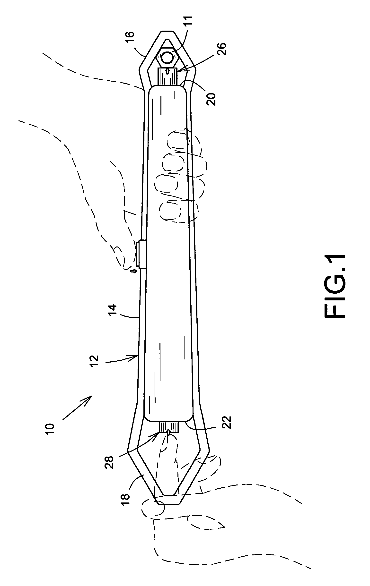
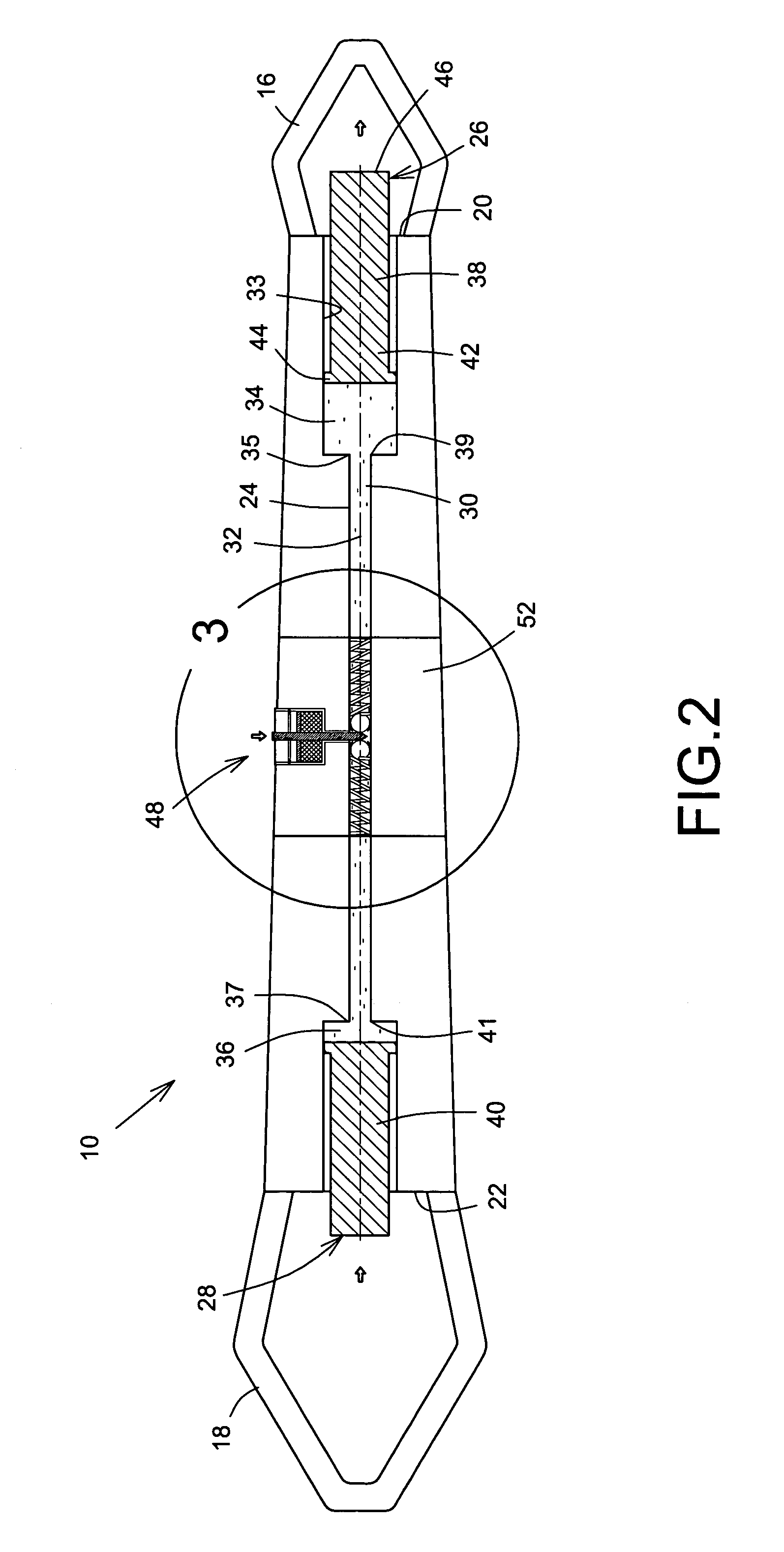
[0004]The present invention reduces the difficulties and disadvantages of the aforesaid designs by providing a tool with an adjusting device, which operates using the non-compressible properties of a liquid located in a confined space. A novel configuration of a liquid-filled passageway and a pair of finger operated pistons permits high retaining forces to be quickly established against a work piece. A valve lock is used to trap the liquid against either of the pistons to lock either of the pistons and to maintain the pistons pressed against the work piece with a large force. Also, fine adjustments are also accessible using the finger operated pistons and lock. Advantageously, the adjusting device permits a user to quickly and efficiently achieve and maintain high torque forces against the work piece without having to re-adjust the tool. Moreover, the number of mechanical components is significantly reduced and as such, the bulk of the tool is significantly reduced. In addition, the aforesaid problems of handle strength being compromised is significantly reduced or essentially eliminated because the liquid filled passageway is narrow compared to the size of the tool body. One additional design features angled ends of the tool, which permit the tool to be used in restricted spaces.

Problems solved by technology

Cavities are often disposed within the tool to house the mechanical components, which compromises the strength of the tool's handle, which is used during leveraging.
Furthermore, tools with mechanical components may not allow for precise adjustability or maintenance of the adjustment once set.

Method used


Image

  • Hand tool adjuster
  • Hand tool adjuster
  • Hand tool adjuster

Examples


Embodiment Construction

[0036]Referring now to FIGS. 1 and 2, an embodiment of an adjusting device of the present invention is shown generally at 10 in use with a hand held tool 12 such as a box end wrench. The tool 12 includes an elongate body 14 with two wrench ends 16, 18 connected to respective body end portions 20, 22. The adjusting device 10 is used to lockingly retain a work piece 11, such as a bolt, nut and the like, in either of the wrench ends 16, 18 once a desired level of retaining tightness is achieved. Although two wrench ends 16, 18 are illustrated throughout, it is to be understood that a single wrench end may be connected to one of the body end portions without deviating from the scope of the invention.

[0037]The wrench ends 16, 18 are typically hexagonally shaped and of different sizes to cooperate with work pieces of different sizes. One skilled in the art will recognize that the wrench ends 16, 18 may also be any shape, which is dictated by the shape and / or type of work piece 11 to be re...


PUM


Abstract

An adjusting device for a tool includes a body with two ends and a fluid filled passageway, which extends between the ends, one end of the body cooperates with a work piece. An actuating member is movably connected to one end of the body, communicates with the fluid in the passageway, and has a surface, which cooperates with the work piece. Another actuating member is movably connected to the other end of the body and communicates with the fluid, and moves the fluid against the first actuating member to extend it. The fluid is locked against the first actuating member so that it retains the work piece in the body end.

Description

FIELD OF THE INVENTION[0001]The present invention concerns an adjusting device, and more particularly to an adjusting device for use in a hand-held tool.BACKGROUND OF THE INVENTION[0002]Adjustable hand-held tools such as wrenches and the like are well known and widely used, either in the home or in industry. The tools typically have mechanically adjustable components, which are hand-operated until a desired torque is applied to a work piece. Hand held tools require certain structural characteristics to be useful for a variety of common applications. The tools need to be ergonomically shaped and sized to permit access of the tool into restricted spaces such as on machinery. In addition, the tools need to be strong and durable to withstand normal operation conditions. Moreover, the mechanism of adjustment should be easy to operate and be able to maintain a precise adjustment. An example of such a mechanically adjustable tool is U.S. Pat. No. 4,787,275, issued Nov. 29, 1988 to Colvin f...

Claims


Application Information

Patent Timeline
IPC IPC(8): B25B13/12B25B13/18B25B23/145
CPCB25B13/18
Inventor ANDERSON, DWAIN
Owner EXPEDITION TOOLS
Learn More