Temperature compensating gas spring

a gas spring and temperature-compensating technology, applied in the field of gas springs, can solve the problems of unattainable numbers, and achieve the effect of increasing or decreasing the working volume, gradual and refined shift in the desired output for

Inactive Publication Date: 2005-12-13
AVM INDS +1
View PDF14 Cites 21 Cited by
  • Summary
  • Abstract
  • Description
  • Claims
  • Application Information

AI Technical Summary

Benefits of technology

[0008]The temperature compensation valves are located adjacent the near the opposite end of the strut. Between the center working chamber and the outer chambers are passages, which provide communication between a working volume and a respective auxiliary volume in the outer cylinder to effectively increase or decrease the working volume of gas within cylinder through communication or isolation of auxiliary volumes. As the working volume is progressively increased by communicating the working volume with the auxiliary volumes in response to progressively lower temperatures, a relatively constant predetermined hold open output force is provided over a wide range of temperature change. Moreover, the gas spring is extremely compact yet provides a heretofore unattainable number of partitioned auxiliary volumes to provide a more gradual and refined shift in desired output force relative to temperature.

Problems solved by technology

Moreover, the gas spring is extremely compact yet provides a heretofore unattainable number of partitioned auxiliary volumes to provide a more gradual and refined shift in desired output force relative to temperature.

Method used


Image

  • Temperature compensating gas spring
  • Temperature compensating gas spring
  • Temperature compensating gas spring

Examples


Embodiment Construction

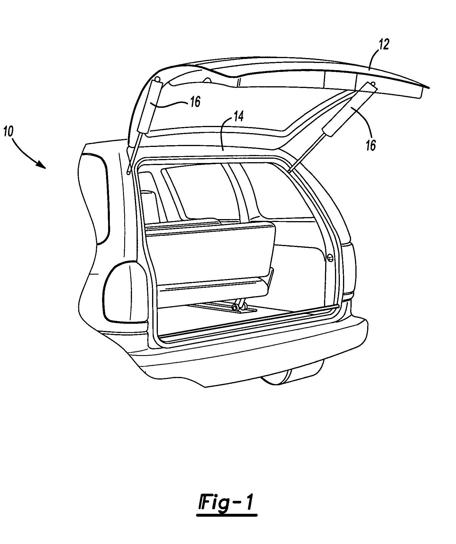
[0015]FIG. 1 illustrates a general perspective view of a vehicle 10 having a closure member 12 which is hinged at an upper edge 14 and supported by a gas spring 16 on each side of the closure member 12 which operates as a counterbalance therefor. The gas spring may, of course, be used in many other applications.

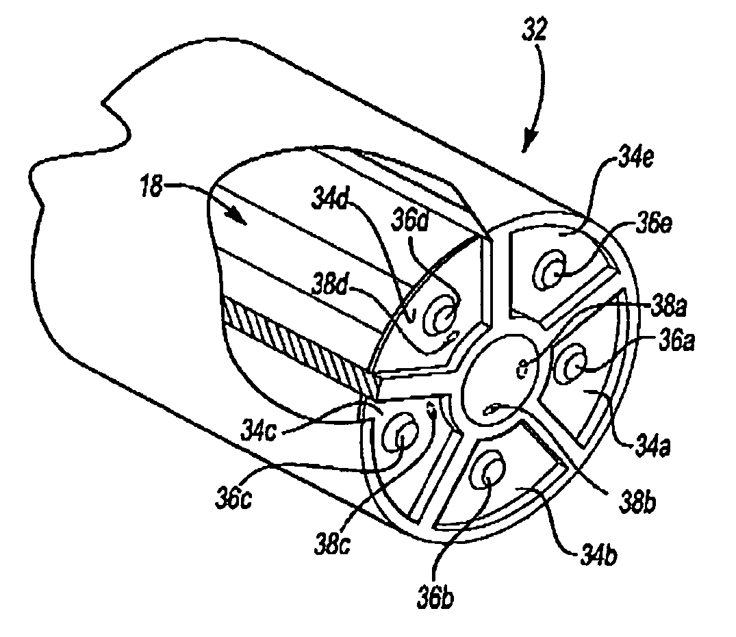
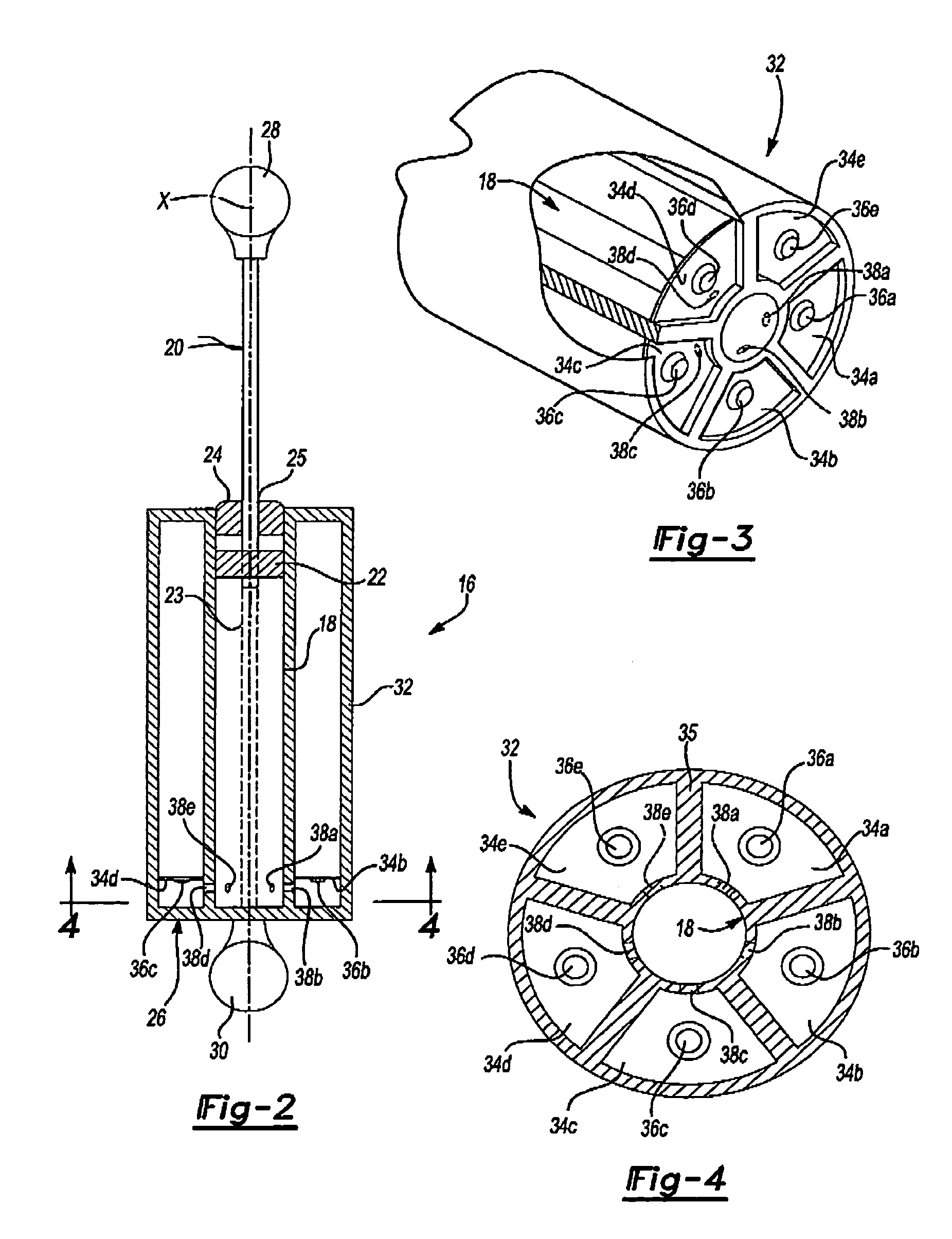
[0016]Referring to FIG. 2, the gas spring 16 generally includes a piston cylinder 18 and a rod 20. A piston 22 is mounted to the rod 20 within a working volume 23 defined by the length of the piston cylinder 18 in which the piston 22 reciprocates.

[0017]The piston 22 reciprocates within the working volume 23 along axis X to separate the working volume 23 within the piston cylinder 18 into two volumes which are filled with gas (e.g., air, nitrogen or some other inert gas) under pressure as generally understood. The piston 22 is constructed to provide controlled by-pass flow of gas from one side of the piston to the other and, as generally understood, the piston provides a relat...


PUM


Abstract

A gas spring provides an outer cylinder which is partitioned into a multiple of auxiliary volumes. A multiple of temperature compensation valves are located within a piston cylinder which sequentially open or close. As the temperature increases, the temperature compensation valves open sequentially and as the temperature decreases the temperature compensation valves close in reverse sequence. Between each pair of adjacent temperature compensation valves is a passage which provides communication between the working volume and an auxiliary volume to effectively increase or decrease the working volume of gas within cylinder through communication with or isolation of the auxiliary volumes.

Description

BACKGROUND OF THE INVENTION[0001]The present invention relates to a gas spring, and more particularly to a gas spring having a multiple of auxiliary volumes located about a central piston cylinder.[0002]Pneumatic or gas springs are utilized in various commercial articles including the automotive industry. Gas springs are also utilized in many other fields to provide a counterbalance force for closure units, such as lids, doors, and cabinets, and amongst others where the gas springs operate as replacements for mechanical spring type fittings. In some fields of use, such as automotive, the change of the surrounding temperature can be quite substantial.[0003]When the temperature drops, the pressure of the gas within the spring unit drops and concurrently therewith the force holding the piston rod extended or in the hold-open position often drops below that required to hold the closure member in an open position. Conversely, at higher temperatures the force is often too high which may m...

Claims


Application Information

Patent Timeline
Patent Type & Authority Patents(United States)
IPC IPC(8): F16F9/00F16F9/32F16F9/34F16F9/52
CPCF16F9/52F16F2224/0216
Inventor BAUMAN, WALTER DOUGLAS
Owner AVM INDS
Why Eureka
Try Eureka