
Adjustable dosage microparticulate feeder for larval and juvenile fishes

a microparticulate and feeder technology, applied in the field of fish feeders, can solve the problems of reducing the quality of fish feed, reducing the number of components, reducing the efficiency of fish feed, and reducing the number of fish feed, etc., to achieve the effect of reducing the number of components, reducing the cost and complexity of the device, and avoiding moisture and caking

Inactive Publication Date: 2015-11-05
THE UNITED STATES OF AMERICA AS REPRESENTED BY THE SECRETARY OF THE COMMERCE
View PDF0 Cites 6 Cited by
  • Summary
  • Abstract
  • Description
  • Claims
  • Application Information

AI Technical Summary

Benefits of technology

The present invention is an improvement on previous feeders used in fish tanks. By separating the dosing dispenser from the terminal delivery, the feed can be protected from the humid environment above the fish tank. A sealed rotating chamber further protects the feed in the hopper from moisture and oxygen between feedings. Additionally, the gas dries both the feed and the tubing and terminal valve during feeding, thus avoiding accumulation of feed on surfaces exposed to the atmosphere. An adjustable portion control is also provided to allow users to adjust the amount of feed dispensed for each fish. This improves the precision of studies utilizing multiple feeders and ensures consistent nutrition for fish.

Problems solved by technology

Microparticulate diets for larval and small juvenile fish pose specific challenges for aquaculturists.
Microparticulate diets, by definition, have a very high specific surface area, making them vulnerable to the effects of oxidation and hydration.
Many of the diet components are often labile and hygroscopic, which further exacerbates the problem.
Fine, hygroscopic particles tend to clump and cake together, and adhere to surfaces with which they come in contact, making rationing and delivery difficult to achieve by automation.
This high leaching rate is a two-edged sword, in that upon contact with the water, nutrients are often lost to solution before the larvae can ingest them.
This technique unfortunately creates an alternating feast and famine situation that is conducive to neither good nutrition nor good hygiene.
Feeding early juvenile fish can be prohibitively expensive in terms of husbandry labor.
Accuracy of ration is paramount in diet trials, where growth and feed conversion are correlated to the diet actually consumed by the fish; therefore feeding the water will not work.
The problem with such a design, as with Cook, the open-ended pipes above fish tanks, may harbor moisture, making such a design unsuitable, particularly for microparticulate feeds, which may cake and clog in the piping.
However, this seems to be an admission that runs of piping with fish feed and moisture contamination could require frequent cleaning.
The problem with this design is that the hoppers need to be refilled over time.
However, such a design results in a large number of expensive components, hoppers, blowers, hoses, and the like, adding to cost and complexity.
The robotic solution is rather costly and over-designed.
The feeder in that embodiment is mounted above the tank, and thus does not solve the problem of moisture contaminating the fish feed.
The most common shortcoming of all these prior feeders is that they don't protect the feed from the effects of moisture and oxygen.
Since most feeders dispense the feed directly above the fish tank, they subject the feed to a highly humid environment.
The hygroscopic nature of larvae feeds results in feed eventually caking and accumulating on the feeder surfaces, resulting in deterioration of both the feed quality, and the accuracy and precision of the dispensed ration.
The challenge then, is to create a feeder that can repeatedly and automatically deliver a small, precise amount of a fragile and functionally difficult material, and protect the feed from the environment when not in use.

Method used


Image

  • Adjustable dosage microparticulate feeder for larval and juvenile fishes
  • Adjustable dosage microparticulate feeder for larval and juvenile fishes
  • Adjustable dosage microparticulate feeder for larval and juvenile fishes

Examples


Embodiment Construction

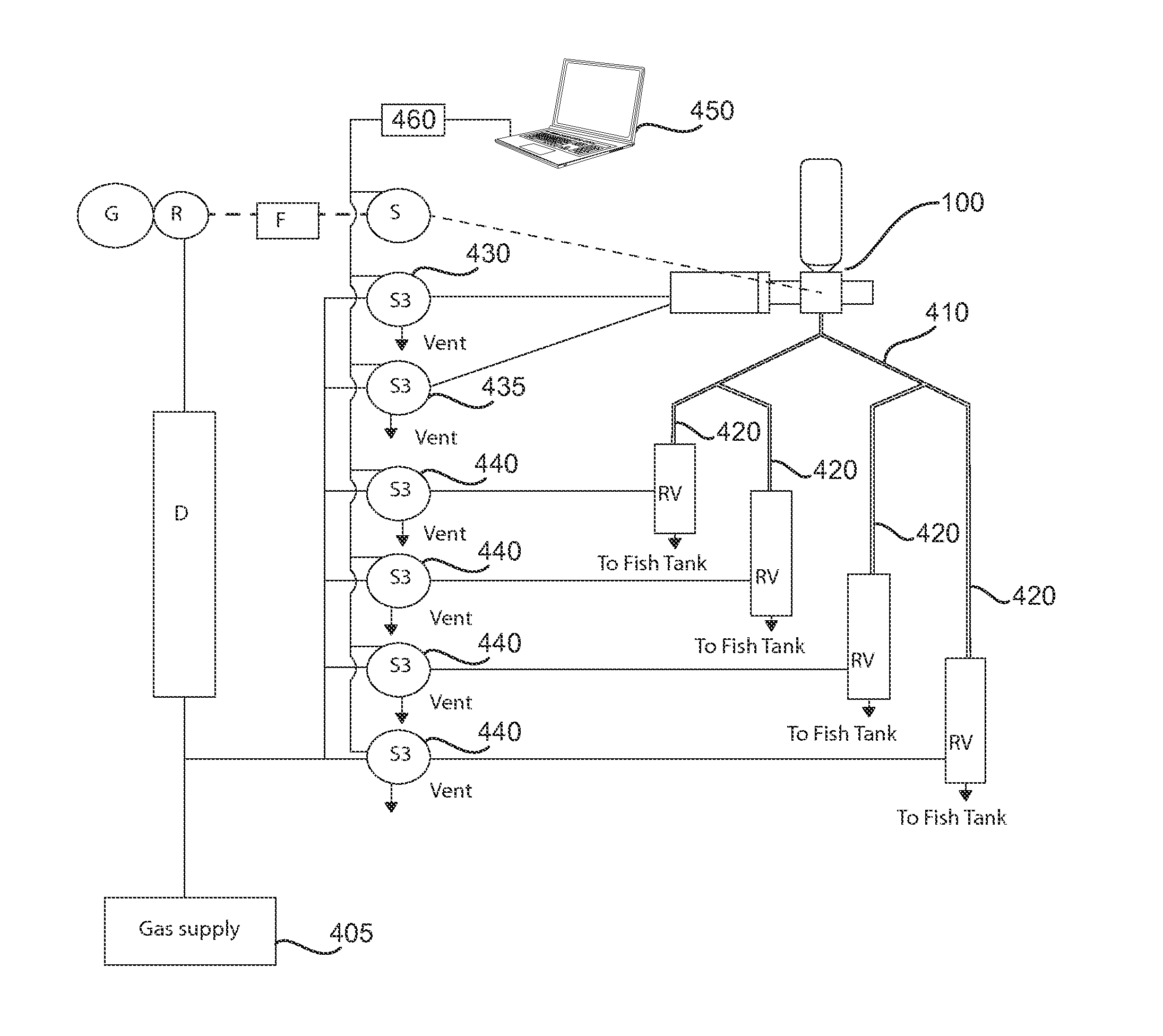
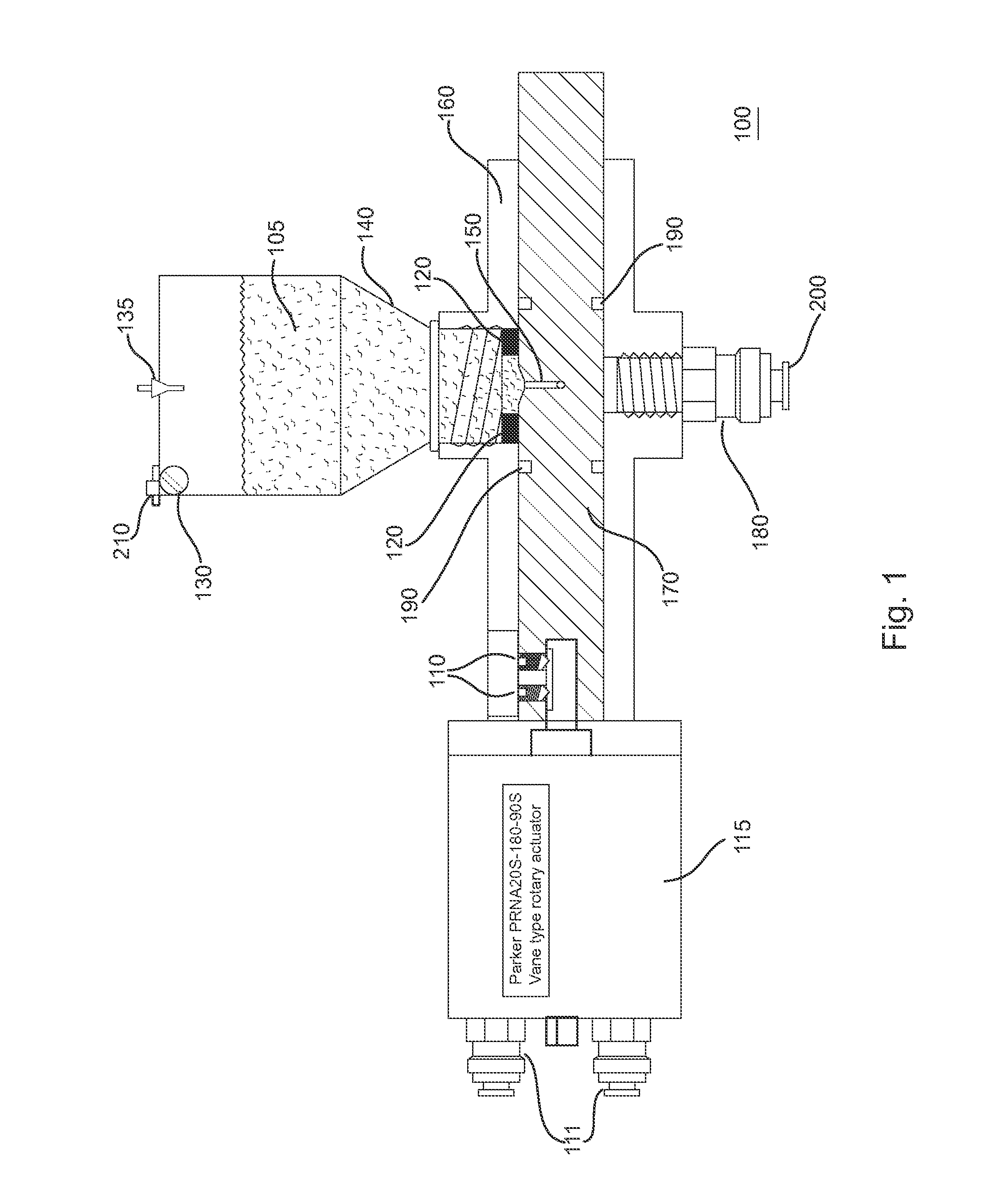
[0047]FIG. 1 is an elevation view of dispenser components of microparticulate feeder. Note that the depicted design uses ‘O’ rings 190 as both seals and bearings. In an alternative embodiment, captive ball bearings and cup seals may be used to ensure long-term performance over a heavy-duty cycle.

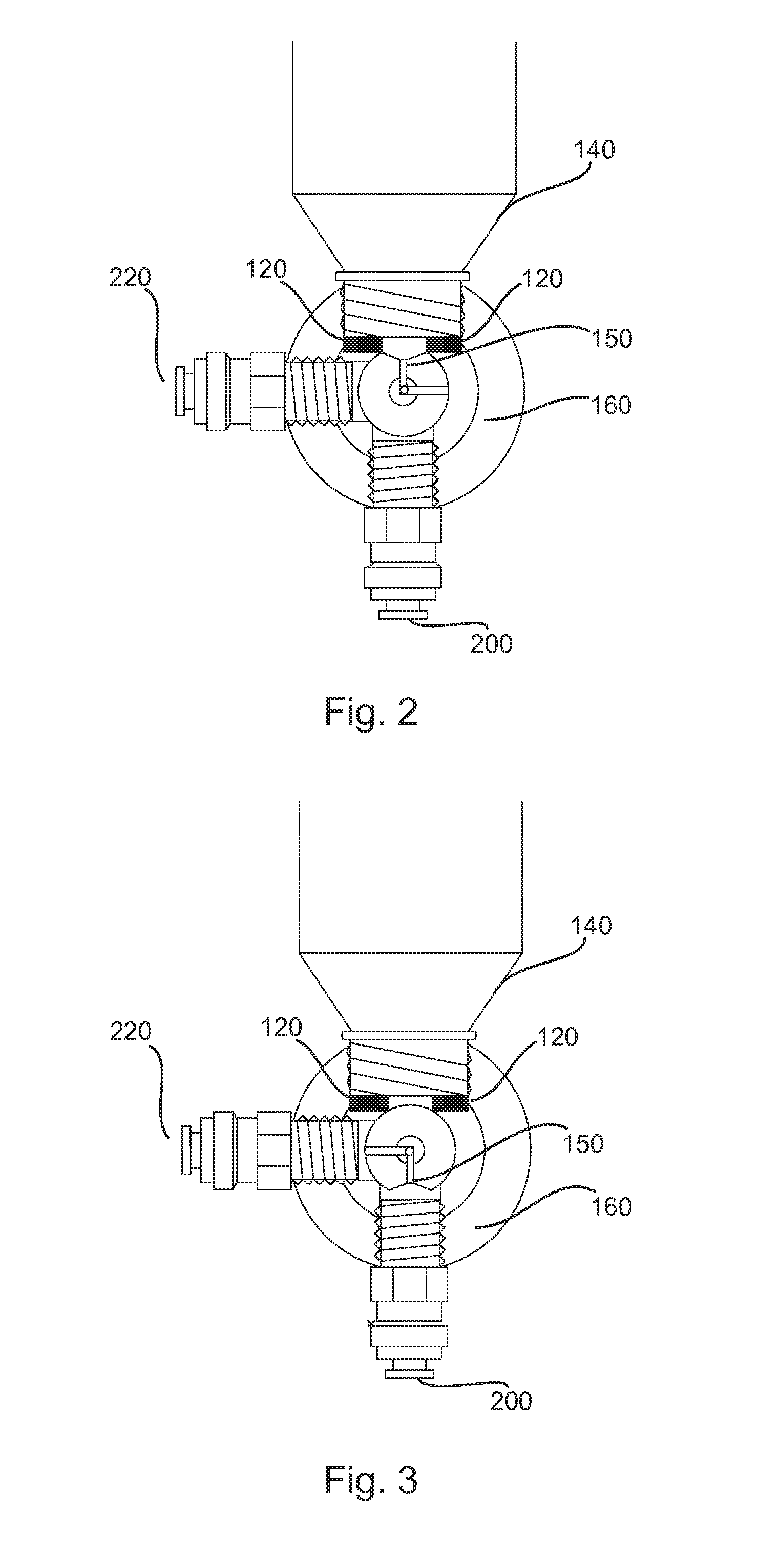
[0048]Referring to FIG. 1, the feeder of the present invention uses a manifold delivery system (as shown in FIG. 4) attached to a central dispensing unit 100. Thus, one feeder can feed several fish tanks. The feeder 100 dispenses a discrete volume of feed 105, determined by a chamber 150 in a rotating component 170, rotating within housing 160. The feed 105 is loaded into the chamber 150 by gravity from a sealed hopper 140 above the chamber 150. A small vibrator 130, attached to the hopper 140, aids in settling the feed into the chamber. Vibrator 140 may comprise a cell phone type vibrator commonly known in the cell phone art. The chamber 150 includes an L-shaped airway radially situated thr...


PUM


Abstract

A feeder for larval and juvenile fishes is capable of delivering an adjustable dose of microparticulate feed to selected locations, via pneumatic conveyance and control. A source of low-pressure dry gas is used to blow microparticulate feed through a manifold and into a selected one of a number of tubes. In order to adjust the portion dispensed by the feeder, an adjustable portion control is provided. Instead of a fixed sized ration cup a threaded recess is provided. Within the recess is provided a mating nylon set screw with an Allen hex head socket. By screwing the set screw in, or out, a user may increase, or decrease the volume of each dose.

Description

CROSS-REFERENCE TO RELATED APPLICATIONS[0001]The present application is a Continuation-In-Part of U.S. patent application Ser. No. 14 / 212,301 filed on Mar. 14, 2014, and incorporated herein by reference.STATEMENT OF GOVERNMENT INTEREST[0002]The research that led to the development of the present invention was sponsored by the National Oceanic and Atmospheric Administration's (NOAA's) National Marine Fisheries Service (NMFS). NOAA is a part of the U.S. Department of Commerce, a component of the U.S. Federal government. The United States Government has certain rights in this invention.FIELD OF THE INVENTION[0003]The present invention relates to fish feeder. In particular, the present invention is directed toward a microparticulate feeder for larval and juvenile fishes.BACKGROUND OF THE INVENTION[0004]Microparticulate diets for larval and small juvenile fish pose specific challenges for aquaculturists. Microparticulate diets, by definition, have a very high specific surface area, makin...

Claims


Application Information

Patent Timeline
Patent Type & Authority Applications(United States)
IPC IPC(8): A01K61/02A01K5/02
CPCA01K61/025A01K5/02A01K61/02A01K5/0291A01K5/0275A01K61/80A01K61/85Y02A40/81
Inventor SCOTT, THOMAS MASHLEY, KENNETH
Owner THE UNITED STATES OF AMERICA AS REPRESENTED BY THE SECRETARY OF THE COMMERCE
Learn More