Device for mixing and/or injecting cements

a technology for injecting cements and mixing tools, which is applied in the field of storing and/or mixing and/or injecting cements, can solve the problems of limited parallel displacement of mixing tools and longitudinal axes, and achieve the effect of reducing abrasion

Inactive Publication Date: 2005-12-13
SYNTHES USA
View PDF17 Cites 46 Cited by
  • Summary
  • Abstract
  • Description
  • Claims
  • Application Information

AI Technical Summary

Benefits of technology

[0007]The present invention attempts to provide a remedy for the disadvantages associated with the prior art. That is, it is an object of the invention to provide a device for mixing a two-component cement, the device including restraining means for the mixing tool so that a minimum distance is maintained between the mixing tool and the wall of the mixing space thereby reducing abrasion on the mixing tool and / or on the wall of the mixing space.
[0025]Because of (1) the distance A of the mixing tool from the front cavity wall, (2) the difference Δ of the mixing tool from the lateral cavity wall, and (3) the distance B of the mixing tool for the front face surface of the piston, the present device ensures that there is no or only very little wear on the cavity wall, the mixing tool and / or on the piston during mixing of the abrasive particles. As previously stated, these distances should advantageously be more than twice the diameter of the particles.
[0031]The present invention provides a device wherein none of the material originating from the mixing container or the mixing tool reaches the material being mixed because of the distance between the mixing tool and the mixing container. This is extremely important for implant materials, since particles of certain materials can lead to undesirable effects in the body. Moreover, the powdery components of the cement can be stored in the inventive device and mixed with the liquid component at the desired time. Subsequently, the mixture can be injected directly from the mixing space to the desired location. Thus, the present device ensures that the material to be mixed is protected at all times from the environment and from possible contaminations therewith.

Problems solved by technology

Furthermore, the device may include restraining means, by means of which the displacement of the mixing tool parallel to the longitudinal axis can be limited at least at the front end of the tube.

Method used


Image

  • Device for mixing and/or injecting cements
  • Device for mixing and/or injecting cements
  • Device for mixing and/or injecting cements

Examples


Embodiment Construction

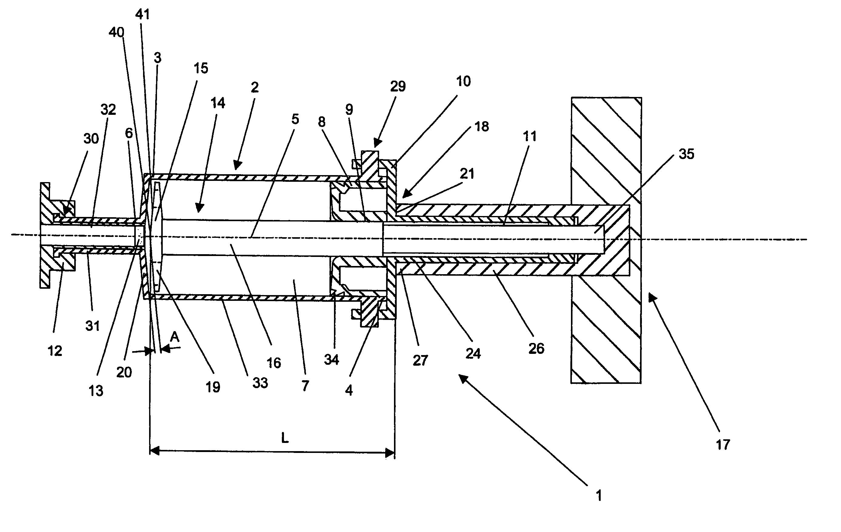
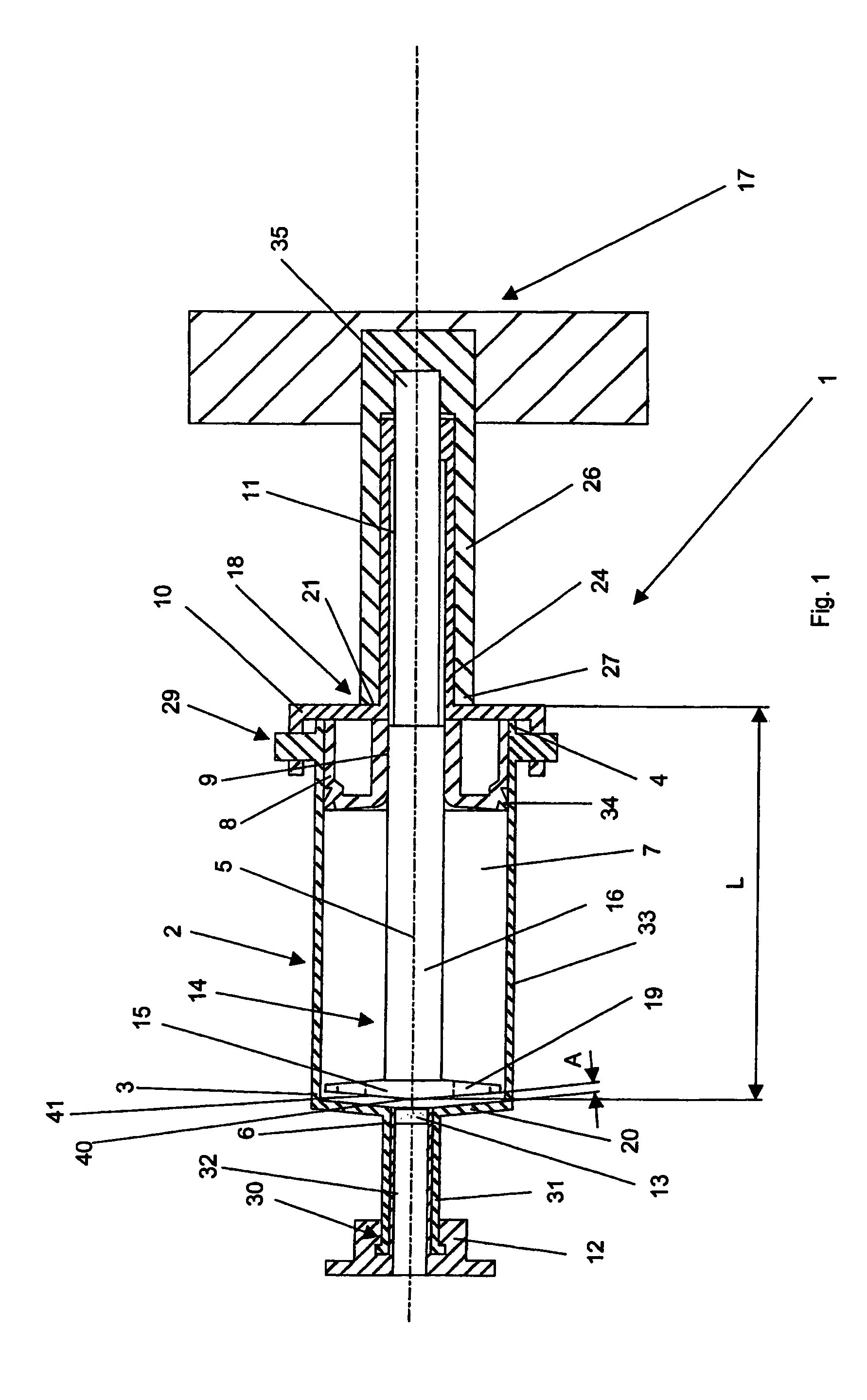
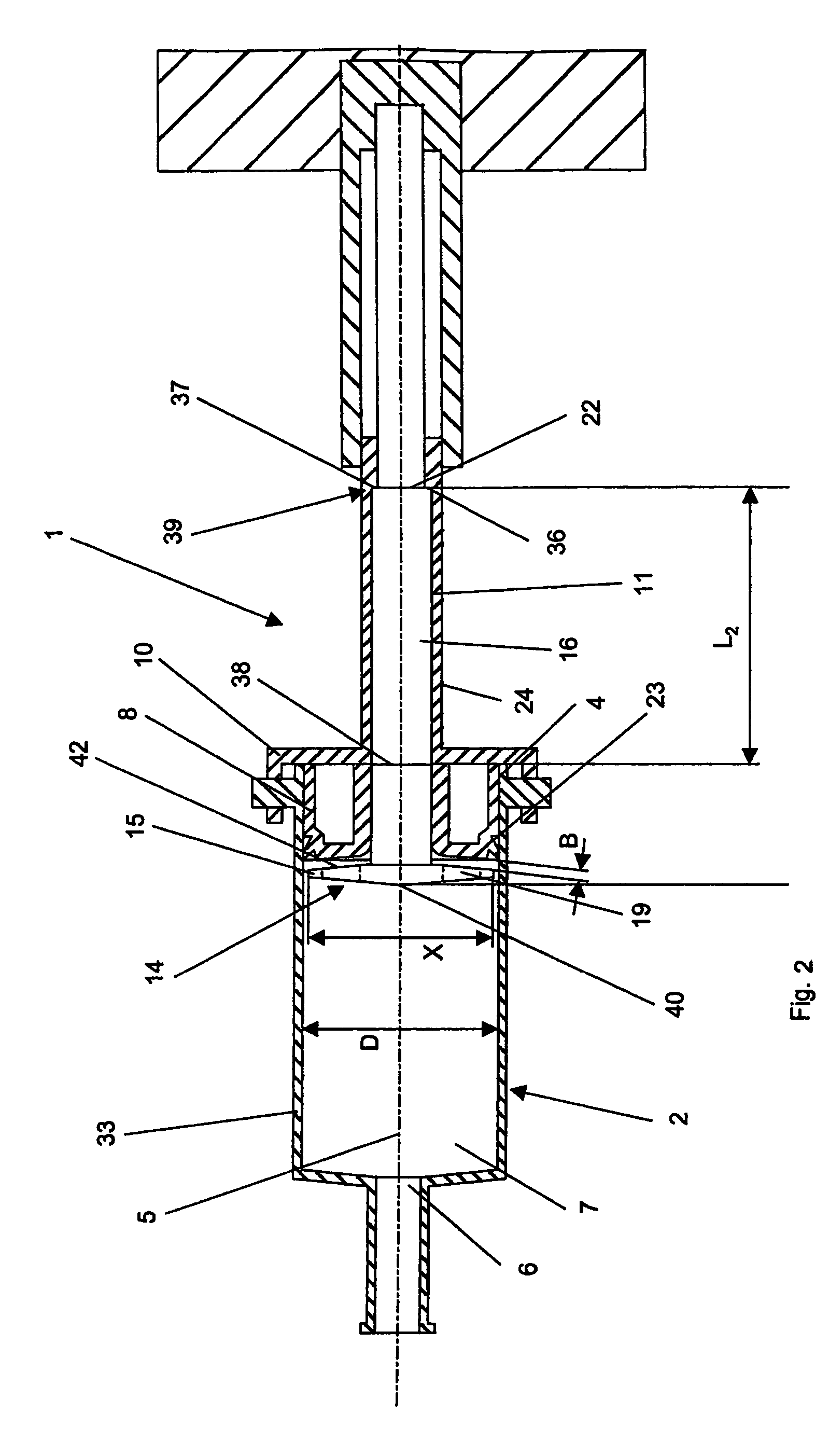
[0035]FIG. 1 shows an embodiment of the inventive device 1 with a tube 2 and a mixer 14, which is shown in its position closest to the front end 3 of the tube 2. The tube 2 is configured with a hollow, cylindrical cavity 7 which is concentric with the longitudinal axis 5. The cavity 7 having a cross sectional area Q extending orthogonal to the longitudinal axis 5. The mixer 14 is axially moveable along the longitudinal axis 5 of the tube 2 and can be rotated about the longitudinal axis 5. The tube 2 includes a front cavity wall 20, which extends generally transverse to the longitudinal axis 5, and a lateral wall 33, which extends generally parallel to the longitudinal axis 5. The front end 3 of the tube 2 has an outlet opening 6 with a cross-sectional area q extending orthogonal to the longitudinal axis 5. The cross-sectional area q of the outlet opening is smaller than the cross-sectional area Q of the cavity 7.

[0036]The rear end 4 of the tube 2 includes a first locking means 29, w...


PUM

PropertyMeasurementUnit
distanceaaaaaaaaaa
distanceaaaaaaaaaa
distanceaaaaaaaaaa

Abstract

The present invention relates to a device for storing and / or mixing and / or injecting cements, especially bone cements. The device includes a tube having a longitudinal axis, a front end with an outlet opening, a rear end; and an internal cylindrical cavity having a first end and a second end; a locking mechanism detachably connected to the front end of the tube so that the outlet opening can be sealed; and a lid detachably connected to the rear end of the tube; the lid having a borehole extending therethrough. The device also includes: a mixer having a mixing shaft sized and configured to extend through the borehole formed in the lid and a mixing tool at one end thereof, the mixer being axially and rotationally moveable inside of the cavity; a driving mechanism connected to the mixer shaft so that the mixer can be axially and rotationally moved with respect to the tube; and a first restraining mechanism for limiting the axial movement of the mixer with respect to the tube so that the a minimum distance A remains between the front face of the mixing tool and the front wall of the cavity; wherein the cylindrical cavity has a diameter D and the mixing tool has a maximum dimension X such that X is less than D.

Description

[0001]Continuation of prior application No.: PCT / CH02 / 00204 filed Apr. 11, 2002.BACKGROUND OF THE INVENTION[0002]The present invention relates to a device for storing and / or mixing and / or injecting cements, especially bone cements.[0003]Many of the present-day cements, which are produced from two components, a powdery component and a liquid component, polymerize after the components are mixed thoroughly and subsequently form a hard and more or less permanent cement composition. Aside from the polymerizable cements, so-called hydraulic cements, such as phosphate cements, may also be used.[0004]Polymethacrylates, which are also referred to as PMMA, are most frequently used as bone cements at the present time. PMMA include a powdery polymer and a liquid monomer. When mixed, these components polymerize within minutes and form a firm connection between the prosthesis and the bone structure surrounding the prosthesis.[0005]In addition, calcium phosphate cements are also increasingly used ...

Claims


Application Information

Patent Timeline
Patent Type & Authority Patents(United States)
IPC IPC(8): A61F2/46A61K38/17B01F11/00B01F13/00B01F15/02C07K14/705C12N1/21C12N15/12G01N33/566
CPCA61B17/8825B01F11/0054B01F13/002B01F13/0023C07K14/705G01N33/566A61B2017/8838B01F15/0266B01F2215/0029G01N2333/726G01N2500/04B01F31/40B01F33/50112B01F33/5011B01F35/75B01F2101/20
Inventor FREI, CHRISTIANEHRSAM, BEAT
Owner SYNTHES USA
Why Eureka
Try Eureka