Connecting part for mounting rails

a technology of connecting parts and mounting rails, which is applied in the direction of flanged joints, branching pipes, building scaffolds, etc., can solve the problems of inability to adjustability, limited attachment on perforated sides, and significant reduction in bearing capacity of mounting rails, etc., and achieves great tolerances and production costs. low

a technology of connecting parts and mounting rails, which is applied in the direction of flanged joints, branching pipes, building scaffolds, etc., can solve the problems of inability to adjustability, limited attachment on perforated sides, and significant reduction in bearing capacity of mounting rails, etc., and achieves great tolerances and production costs. low

US6974276B2Inactive Publication Date: 2005-12-13HALFEN GMBH & CO KG

Image

  • Connecting part for mounting rails
  • Connecting part for mounting rails
  • Connecting part for mounting rails

Examples


Embodiment Construction

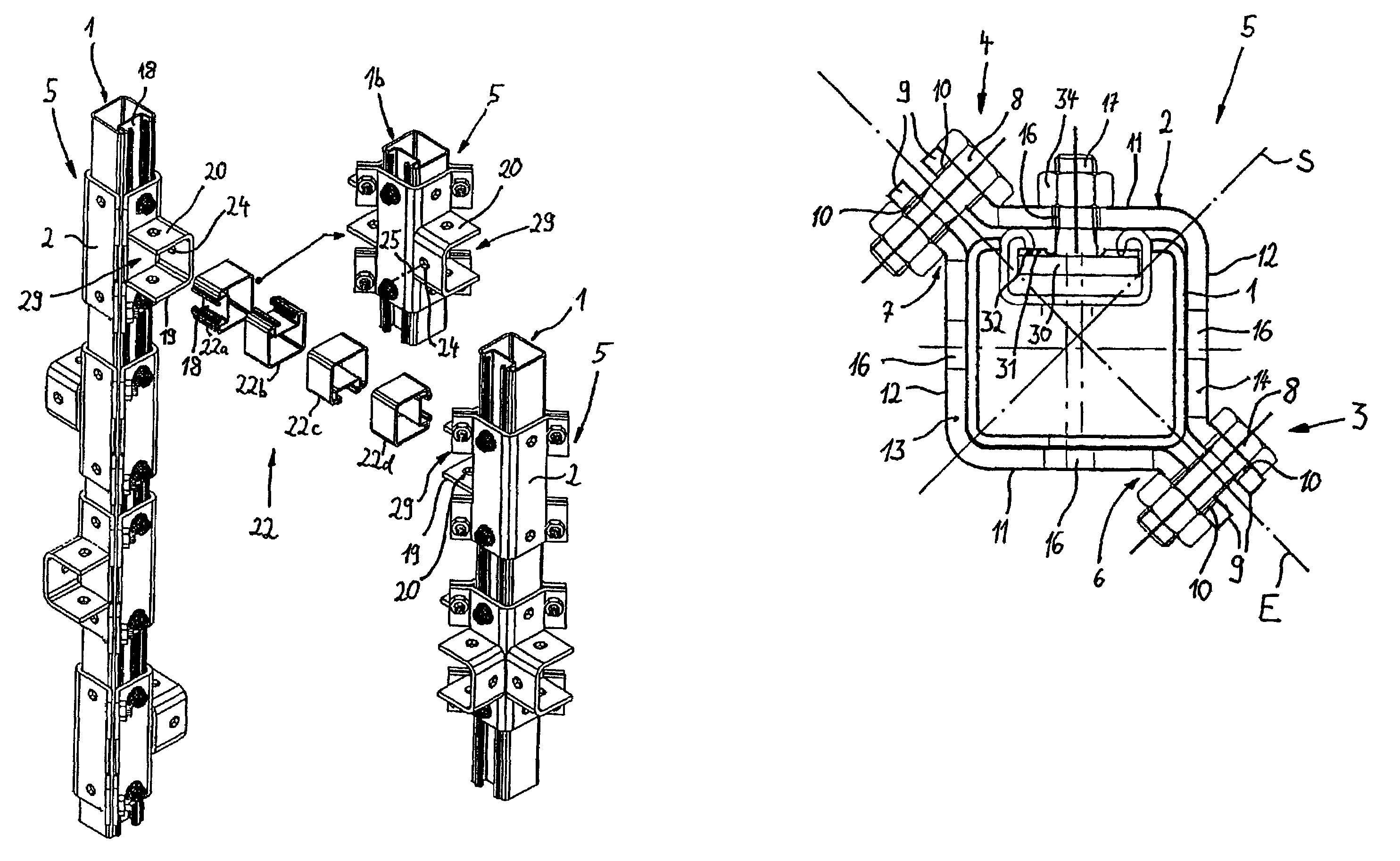
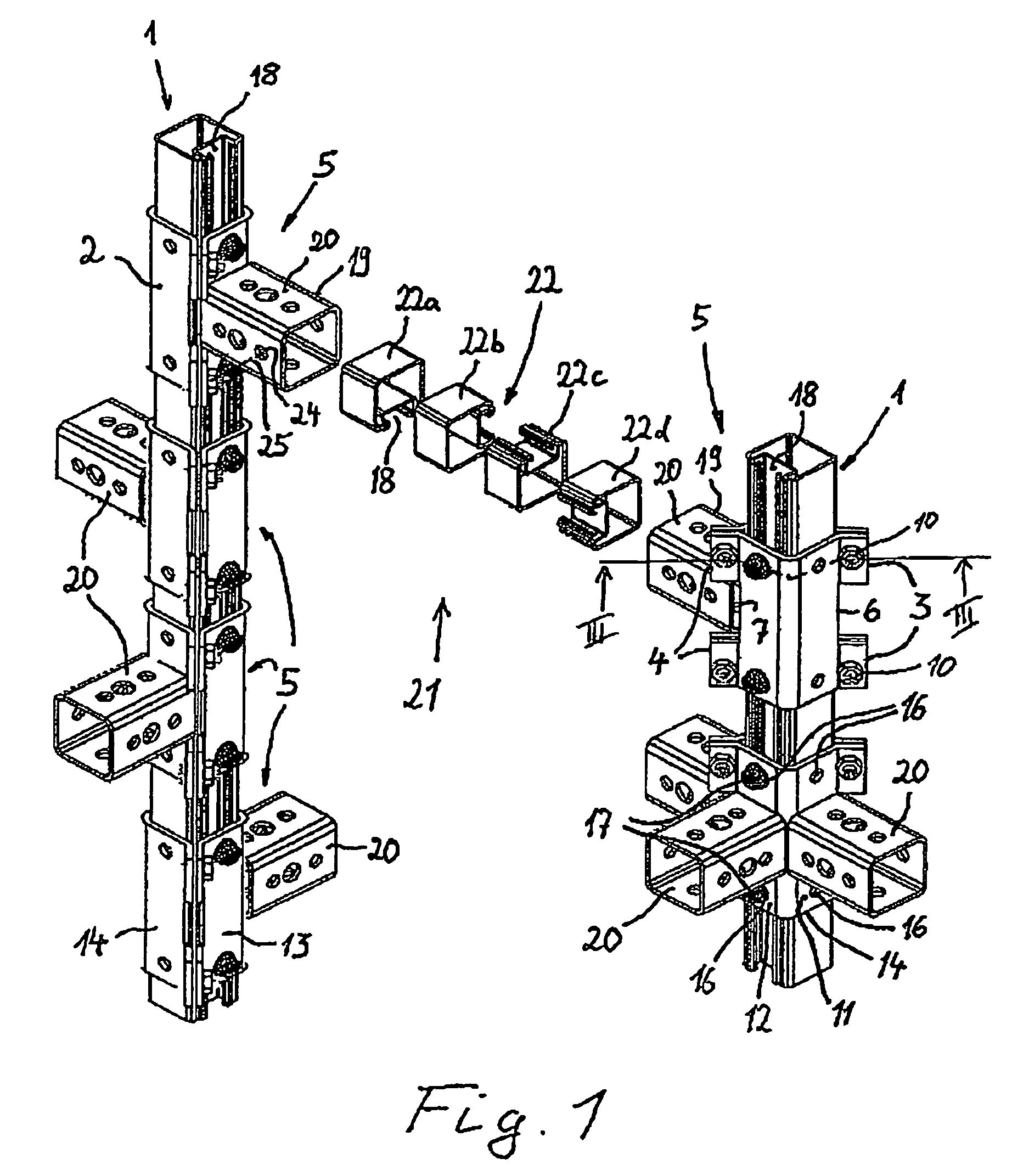
[0041]FIG. 1 shows in a perspective illustration showing a schematic exploded view a frame construction of two vertical mounting rails 1 between which a transverse support 21 is horizontally positioned. The transverse support 21 is secured by a connecting part 5 on the two mounting rails 1, respectively. The connecting parts 5 securing the transverse support 21 are comprised of fastening parts 2 surrounding the mounting rail 1 on all sides and comprising securing means 19 in the form of a support receptacle 20 for the transverse support 21. The support receptacles 20 have a plurality of bores 24 for the indicated fastening screws 25. The transverse support 21 is formed as a mounting rail 22 of the same kind as the mounting rail 1 and comprises a rail slot 18. The mounting rail 22 can be mounted in different relative orientations relative to the support receptacle 20, illustrated by four segments 22a, 22b, 22c, 22d of the mounting rail 22 showing the different positions of the rail s...


PUM


Abstract

A connecting part for attachment on a mounting rail has a fastening part with an at least approximately rectangular cross-section. The fastening part has legs and surrounds when mounted a mounting rail on all sides by having a matching cross-section formed by the legs. The fastening part has clamping devices for effecting a clamping fixation of the connecting part on the mounting rail. A cross-sectional plane of the fastening part has two diagonally opposed corners and the clamping devices are arranged on the two diagonally opposed corners, respectively.

Description

CROSS REFERENCE TO RELATED APPLICATIONS[0001]This is a continuation of International Application PCT / EP01 / 09948 with an international filing date of Aug. 29, 2001, not published in English under PCT Article 21(2), and now abandoned.BACKGROUND OF INVENTION[0002]The invention relates to a connecting part for attachment onto a mounting rail.[0003]Mounting rails are used in construction technology for multiple purposes. Such mounting rails, connected by suitable connecting parts with one another, enable the construction of frames or consoles with cantilevered arms on which, for example, installations such as pipes, conduits or the like can be fastened. With a suitable selection of different connecting parts, corresponding configurations can be mounted on site according to a modular principle, without this requiring pre-manufacture, for example, in a shop. Because of the easy and adjustable assembly, corresponding mounting rail systems are used frequently, for example, in pipeline constr...

Claims


Application Information

Patent Timeline
13 Dec 2005
Publication
US6974276B2
IPC
A47B57/54; F16B7/04; E04B1/58
CPC
A47B57/54; F16B7/0486; Y10T403/7062; Y10T403/64; Y10T403/581; Y10T403/7105; Y10T403/7111; Y10T403/535
Inventors
KIRCHNER, GEORG; BINNA, MICHAEL