
Reduced power consumption clock network

Inactive Publication Date: 2005-12-13
ALTERA CORP
View PDF7 Cites 23 Cited by
  • Summary
  • Abstract
  • Description
  • Claims
  • Application Information

AI Technical Summary

Problems solved by technology

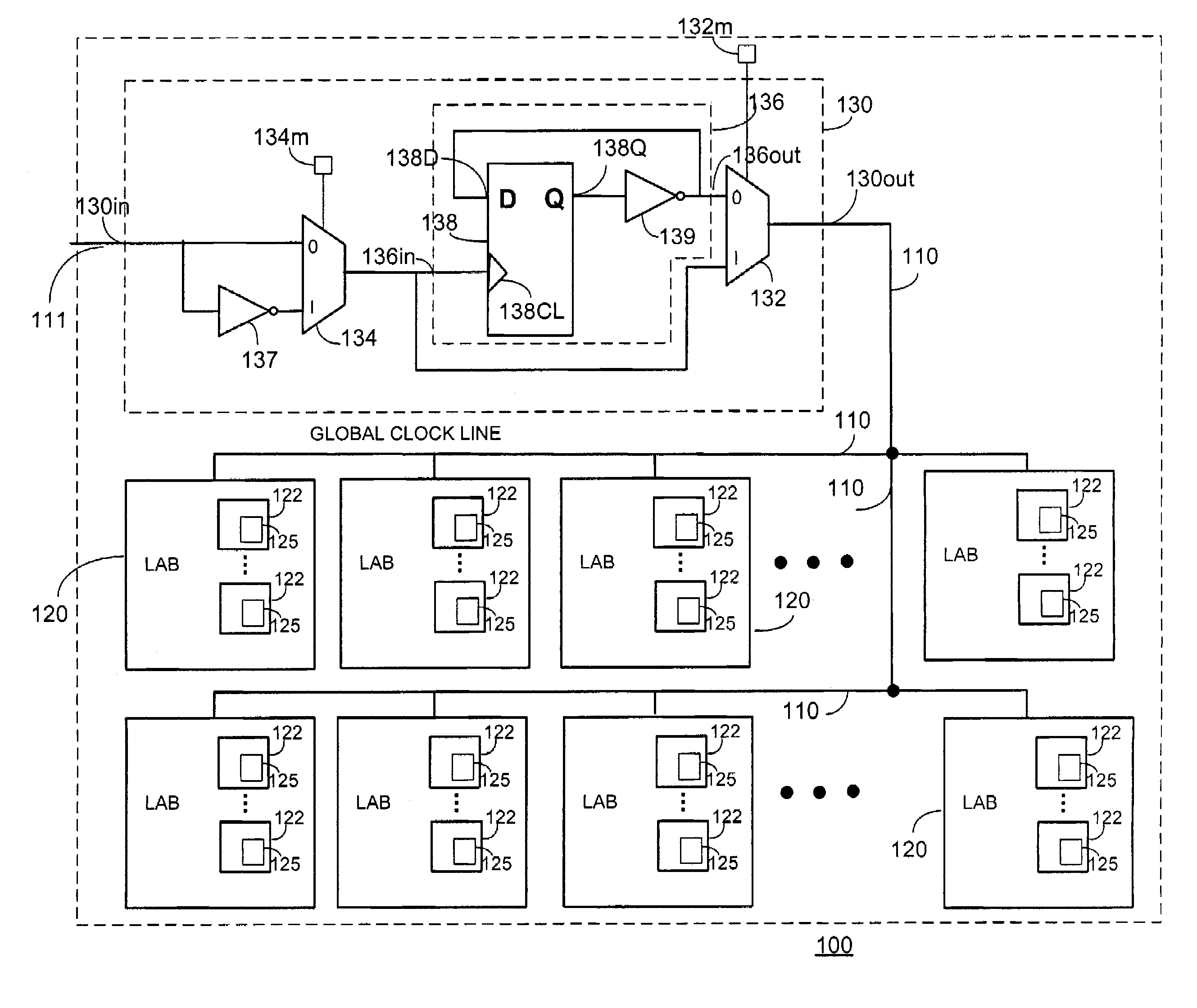
Because they typically fan out to every logic element in the device, clock networks can consume considerable power.
Some of this power dissipation occurs in the wiring and driving transistors of the global clock network outside and between the LABs, and some of the power dissipation occurs in the wiring and devices that exist inside each LAB and its associated logic elements.

Method used


Image

  • Reduced power consumption clock network
  • Reduced power consumption clock network
  • Reduced power consumption clock network

Examples


Embodiment Construction

[0016]The following description is presented to enable any person skilled in the art to make and use the invention, and is provided in the context of particular applications and their requirements. Various modifications to the exemplary embodiments will be readily apparent to those skilled in the art, and the generic principles defined herein may be applied to other embodiments and applications without departing from the spirit and scope of the invention. Thus, the present invention is not intended to be limited to the embodiments shown, but is to be accorded the widest scope consistent with the principles and features disclosed herein.

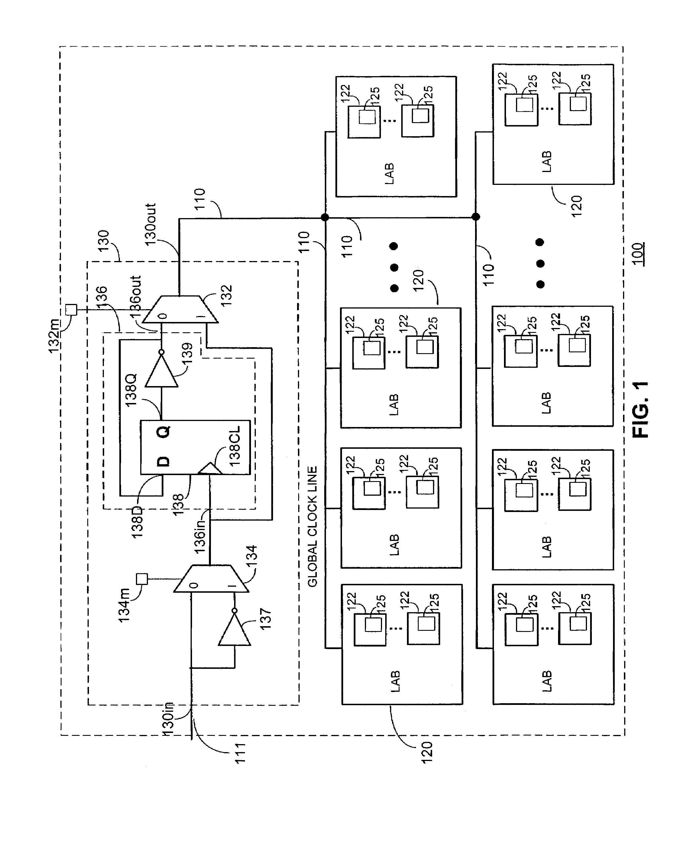
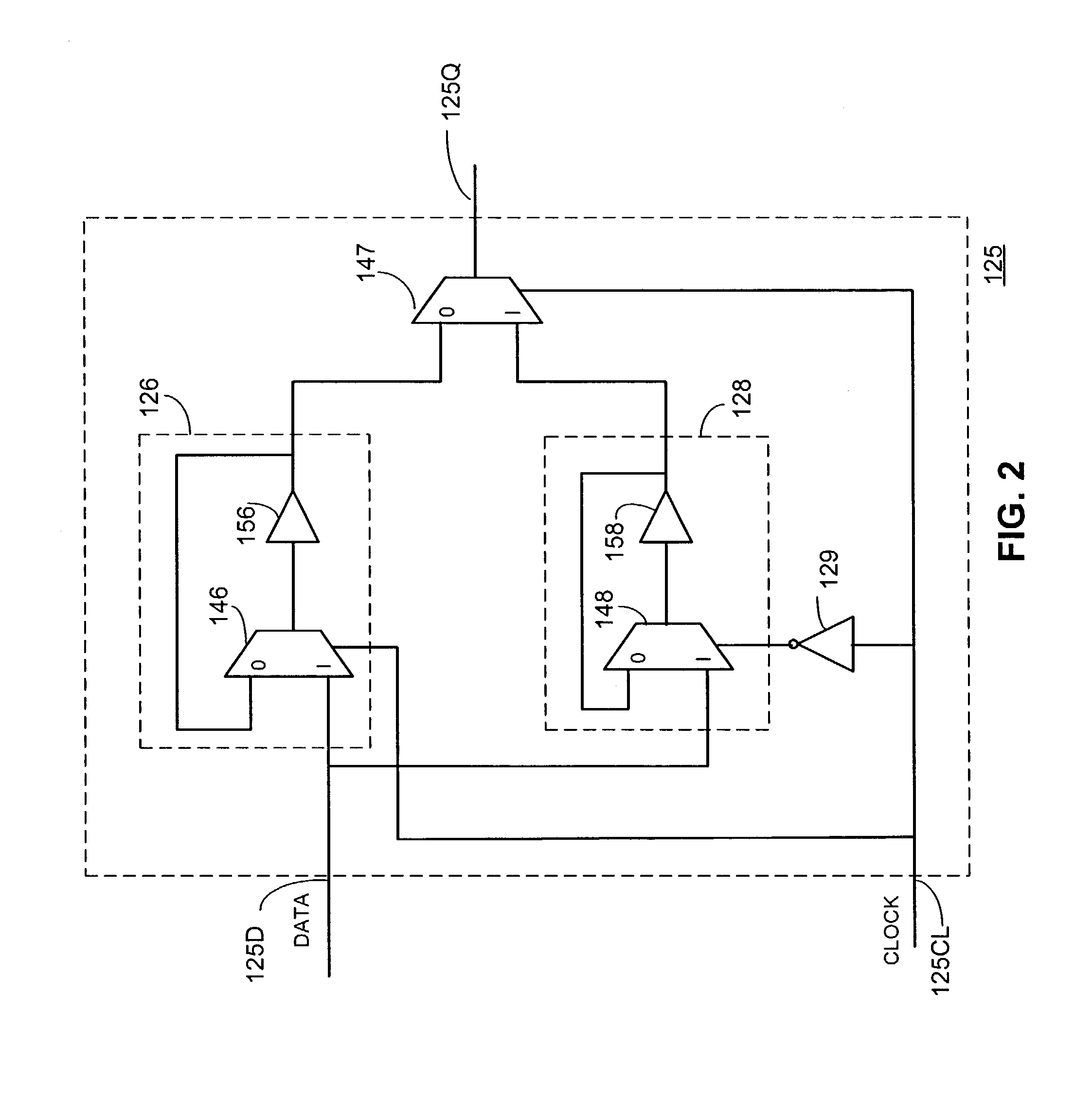
[0017]FIG. 1 illustrates a PLD portion 100 in accordance with an embodiment of the present invention. PLD portion 100 includes frequency divider circuit 130, clock distribution network 110, and a plurality of LABs 120. Each LAB 120 includes a plurality of logic elements 122 and each logic element includes one or more registers 125. Registers 125 are d...


PUM


Abstract

An exemplary reduced-power-consumption network includes a frequency divider coupled through global clock lines to a plurality of double-edge triggered registers. Another exemplary network includes a plurality of individually programmable frequency dividers coupled through local clock lines to a plurality of double-edge triggered registers.

Description

BACKGROUND OF THE INVENTION[0001]The present invention relates to clock networks and associated registers for use with programmable logic devices or other similar devices.[0002]Programmable logic devices (“PLDs”) (also sometimes referred to as CPLDs, PALs, PLAs, FPLAs, EPLDs, EEPLDs, LCAs, FPGAs, or by other names), are well-known integrated circuits that provide the advantages of fixed integrated circuits with the flexibility of custom integrated circuits. Such devices are well known in the art and typically provide an “off the shelf” device having at least a portion that can be electrically programmed to meet a user's specific needs. Application specific integrated circuits (“ASICs”) have traditionally been fixed integrated circuits, however, it is possible to provide an ASIC that has a portion or portions that are programmable; thus, it is possible for an integrated circuit device to have qualities of both an ASIC and a PLD. The term PLD as used herein will be considered broad en...

Claims


Application Information

Patent Timeline
IPC IPC(8): G06F1/10G06F1/32
CPCG06F1/10G06F1/32
Inventor PEDERSEN, BRUCE
Owner ALTERA CORP
Learn More