Apparatus and method for "seeing" foot inside of shoe to determine the proper fit of the shoe

a technology of shoe shoe and foot, applied in the field of shoe shoe shoe fitting apparatus and method, can solve the problems of subjective selection and sizing of shoes, and achieve the effects of low cost, low maintenance, and low construction cos

Inactive Publication Date: 2005-12-13
MCKENNA LOU
View PDF20 Cites 46 Cited by
  • Summary
  • Abstract
  • Description
  • Claims
  • Application Information

AI Technical Summary

Benefits of technology

[0023]An advantage of the present invention is that the proper fit of a shoe may be determined.
[0031]Another advantage of the present invention is that the present thermographic infrared apparatus minimizes the return of shoes that do not fit and therefore is fiscally self-supporting.

Problems solved by technology

The picking and sizing of shoes is problematic and subjective.

Method used


Image

  • Apparatus and method for "seeing" foot inside of shoe to determine the proper fit of the shoe
  • Apparatus and method for "seeing" foot inside of shoe to determine the proper fit of the shoe
  • Apparatus and method for "seeing" foot inside of shoe to determine the proper fit of the shoe

Examples


Embodiment Construction

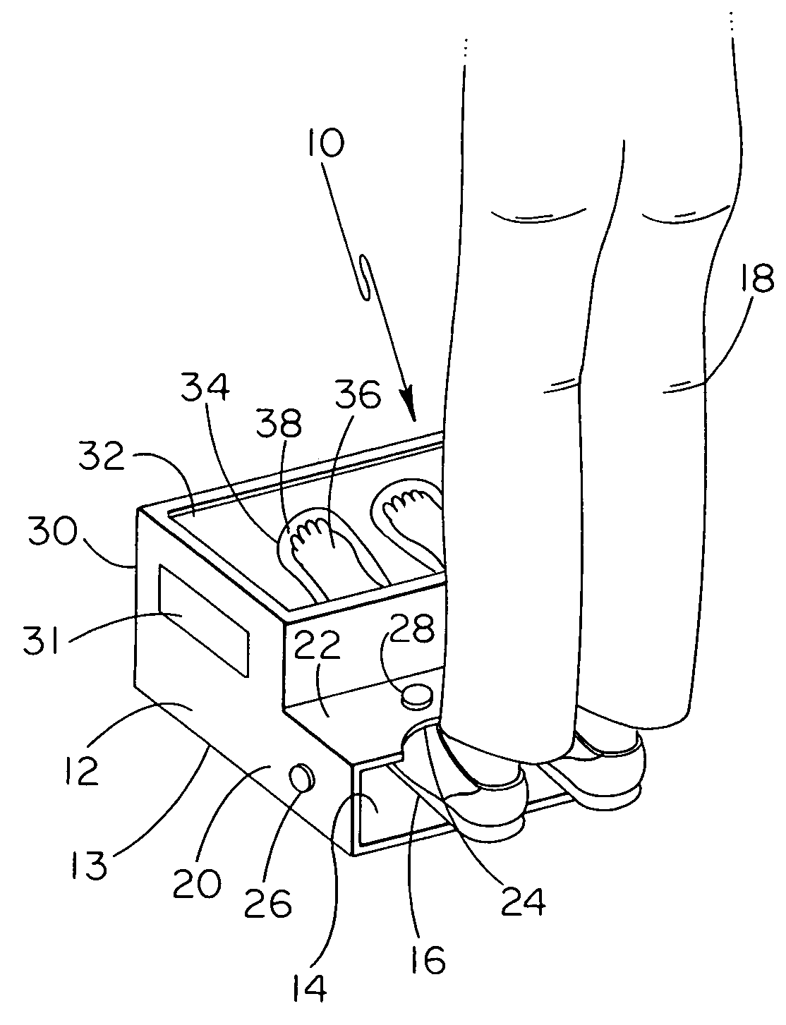
[0053]Thermographic Infrared Apparatus 10

[0054]In accordance with the preferred embodiment of the present invention, as shown in FIG. 1, the present thermographic infrared apparatus or imaging radiometer is indicated in general by reference number 10. The thermographic infrared apparatus 10 includes a housing 12. Housing 12 includes a first portion 13 having a base or floor 14 adapted for the shoes 16 being worn by a person 18. The first portion 13 of the housing 12 further is defined by a pair of sides 20 and a ceiling or upper shroud 22 running to and between the sides 20 and being disposed opposite of the base or floor 14. The ceiling 22 includes a pair of curved recesses 24 formed therein where each of the recesses 24 may include an ankle or shin of a leg of person 18. Each of the sides 20 has engaged thereto a thermographic infrared instrument 26 for capturing a view of a side of a shoe being worn by person 18. The ceiling 22 has engaged thereto a thermographic infrared instrum...


PUM


Abstract

A thermographic infrared apparatus and method for seeing, and thus measuring, a foot inside of a shoe. The apparatus includes one or more thermographic instruments aimed at a base for capturing one or more thermographic images or fields of view of a shoe on the base and thus the heat transferred to the shoe from the foot. The apparatus further includes a display mounted above the base and aimed at the eye level of a person standing on the base such that the person can determine from the thermographic image how well the shoe or shoes fit. The method includes one or more of the steps of taking a thermal infrared image of a shoe on a foot, taking a thermal infrared image of a foot having no shoe thereon, taking a thermal infrared image of a shoe having no foot therein, taking a thermal infrared image from a first direction, taking a thermal infrared image from a second direction to capture surfaces hidden from the first direction, and then comparing one or more of the thermal infrared images. Other imaging methods for determining proper fit of a shoe include low dose x-ray, backscattering x-ray, microwave, acoustic, radio, and ultrasound imaging methods.

Description

BACKGROUND OF THE INVENTION[0001]The present invention relates generally to an apparatus and method for determining proper fit of a shoe, particularly to such an apparatus and method utilizing differences in temperature on the outer surface of the shoe, and specifically to such an apparatus and method utilizing infrared thermal infrared apparatus and methods.[0002]Electromagnetic radiation is the emission of energy from a source. The visible portion of the electromagnetic spectrum includes radiation having wavelengths from about 0.38 micrometers to about 0.72 micrometers. The infrared portion of the electromagnetic spectrum includes radiation having wavelengths from about one micrometer to about 1000 micrometers.[0003]The infrared portion of the electromagnetic spectrum is further divided into two sections, the near infrared section and the thermal infrared section. The near infrared section includes radiation having wavelengths from about one micrometer to about four micrometers. N...

Claims


Application Information

Patent Timeline
Patent Type & Authority Patents(United States)
IPC IPC(8): A43D1/02G08B23/00
CPCA43D1/025
Inventor MCKENNA, LOU
Owner MCKENNA LOU
Why Eureka
Try Eureka