Image quality detecting apparatus, image forming apparatus and method, and image quality controlling apparatus and method

a technology of image quality and detection apparatus, which is applied in the direction of electrographic process apparatus, instruments, printing, etc., can solve the problems of inability to obtain information related to graininess or information, no reports on measures to detect image quality, and deterioration of graininess, so as to reduce density unevenness, reduce density unevenness, and reduce density unevenness

Inactive Publication Date: 2005-12-13
RICOH KK
View PDF29 Cites 41 Cited by
  • Summary
  • Abstract
  • Description
  • Claims
  • Application Information

AI Technical Summary

Benefits of technology

[0030]The image forming apparatus according to still another aspect of this invention includes an image carrier, a developer carrier that carries a developer for developing an image formed on the image carrier to make the image visible, and a density unevenness detecting unit that detects density unevenness of the image in a spatial frequency range including a spatial frequency in which human eyesight is the most sensitive. The image forming apparatus also includes a density detecting unit that detects an average density of the image, and a control unit that changes at least one of toner density of the developer and developing potential so as to reduce the density unevenness, based on detection results obtained from the density unevenness detecting unit and the density detecting unit.
[0031]The image forming apparatus according to still another aspect of this invention includes an image carrier, a developer carrier that carries developer for developing an image formed on the image carrier to make the image visible, and a density unevenness detecting unit that detects density unevenness of the image in a spatial frequency range including a spatial frequency in which human eyesight is the most sensitive. The image forming apparatus also includes a density detecting unit that detects an average density of the image, and a control unit that changes at least one of a linear velocity ratio of the developer carrier to the image carrier and developing potential so as to reduce the density unevenness, based on detection results obtained from the density unevenness detecting unit and the density detecting unit.
[0032]The image forming apparatus according to still another aspect of this invention includes an image carrier, a toner carrier that carries toner for developing an image formed on the image carrier to make the image visible, and a density unevenness detecting unit that detects density unevenness of the image in a spatial frequency range including a spatial frequency in which human eyesight is the most sensitive. The image forming apparatus also includes a density detecting unit that detects an average density of the image, and a control unit that changes at least one of a linear velocity ratio of the toner carrier to the image carrier and developing potential so as to reduce the density unevenness, based on detection results obtained from the density unevenness detecting unit and the density detecting unit.

Problems solved by technology

The graininess is largely determined by an initial image forming condition, however, in addition it is well known that the graininess deteriorates with time.
However, there have been no reports on measures to detect the image quality focusing on the graininess so far.
Further, even though the invention disclosed in JPA No.H6-27776 is provided with a process to compute space modulation transfer function (MTF) in a computing process, it is impossible to obtain information related to the space frequencies of image unevenness in this computation, consequently it is impossible to obtain information related to the graininess or information that has a strong correlation with the graininess.
However, none of the inventions mentioned here controls the image forming conditions based on information for the graininess (density unevenness) of the image.
As explained above, in the conventional technology, the image forming conditions are not controlled in consideration of the graininess of toner, and therefore it is impossible to take countermeasures against deterioration of the graininess.
In other words, the conventional technology is not provided to have such image quality detecting unit and image quality restoration unit, thus the developer or photoreceptors have to be inevitably replaced after reaching a certain operating hours estimated during a stage of development of the image forming apparatus.

Method used


Image

  • Image quality detecting apparatus, image forming apparatus and method, and image quality controlling apparatus and method
  • Image quality detecting apparatus, image forming apparatus and method, and image quality controlling apparatus and method
  • Image quality detecting apparatus, image forming apparatus and method, and image quality controlling apparatus and method

Examples


first embodiment

[0101]this invention will be explained below.

[0102]1.1 General Structure

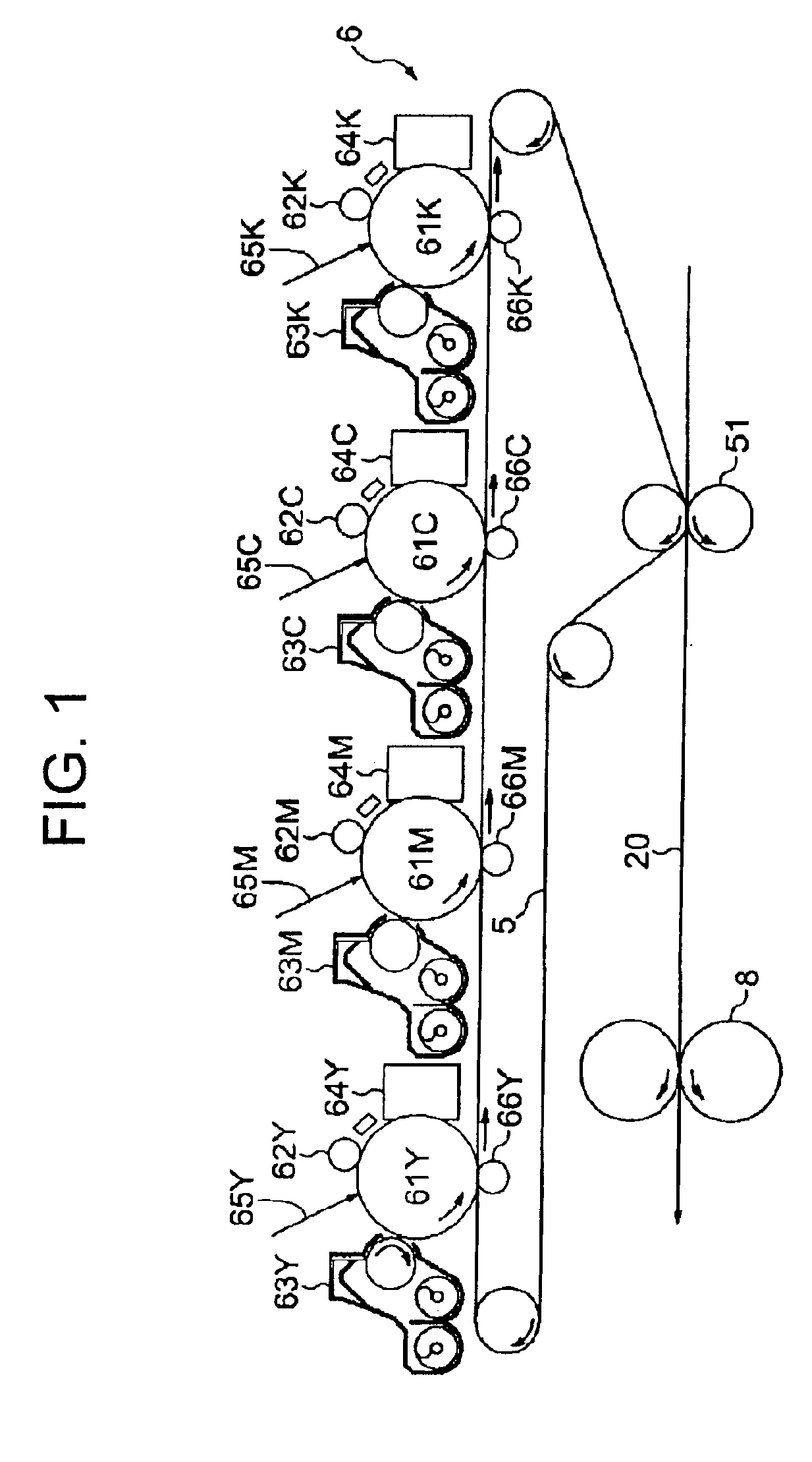
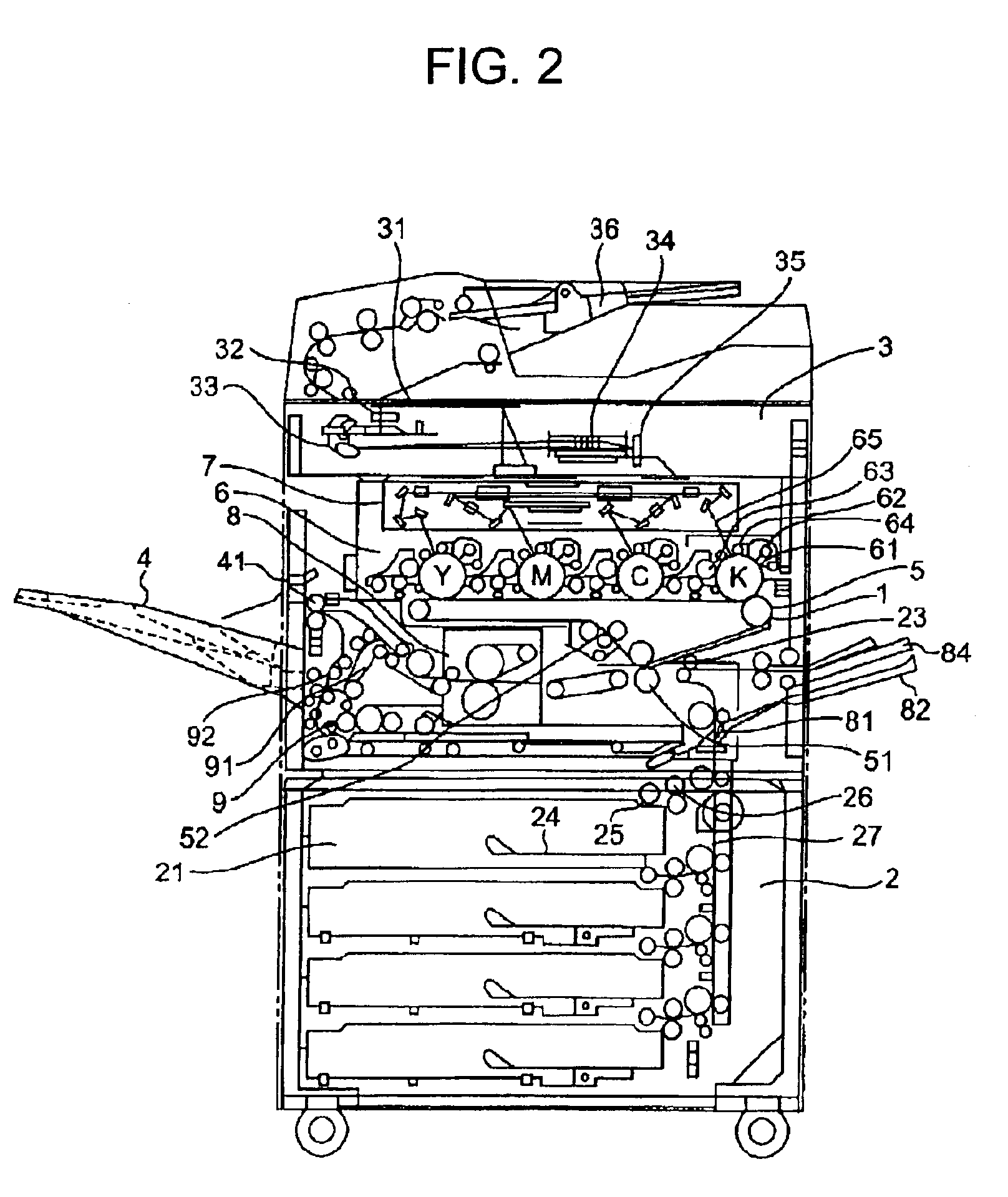
[0103]FIG. 1 shows an image forming unit of a full-color image forming apparatus of a dry type two-component developing system that is furnished with tandem arranged photoreceptor drums as latent image carriers according to the first embodiment. FIG. 2 is a general view of the full-color image forming apparatus equipped with the image forming unit.

[0104]As shown in FIG. 2, the image forming unit 1 is disposed at about a center of the tandem type color image forming apparatus MFP according to the first embodiment, and a paper feeding unit 2 is disposed beneath the image forming unit 1, and the paper feeding unit 2 includes a plurality of trays 21. Furthermore, a reading unit 3 to read a document is arranged above the image forming unit 1. A paper discharging tray 4 as a discharged paper storage unit is equipped in downstream of a paper transfer direction (shown in the left side of FIG. 2), and is loaded with disc...

second embodiment

[0201]this invention will be explained below.

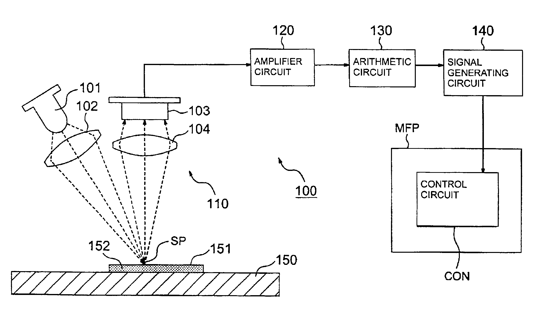
[0202]In the first embodiment, an example in which a spot is collected on the image pattern 151 with the collective lens 102 as shown in FIG. 6 and light reflected from the image pattern is collected on the image formation surface of the photoelectric conversion element 103 through the image forming lens 104, is explained. However, it is possible to guide light through an optical fiber as shown in FIG. 36. FIG. 36 is a schematic diagram of an image quality measuring apparatus according to the second embodiment. The example shown in FIG. 36 is different from the first embodiment shown in FIG. 6 in that a first optical fiber 105 and a second optical fiber 106 and an objective lens 107 are disposed in the apparatus. Therefore, only the different points will be explained.

[0203]That is to say, in the second embodiment, an end of the first optical fiber 105 is disposed at a light collecting point of the collective lens 102, and the other end of...

third embodiment

[0208]this invention will be explained below.

[0209]This embodiment is an example of the image forming apparatus furnished with the tandem type image forming units shown in FIG. 1 that is provided with the image quality measuring apparatus in the second embodiment. FIG. 38 shows a structure of the third embodiment.

[0210]As shown in FIG. 38, the third embodiment is provided to detect the quality of an image on the photoreceptor 61 and the quality of an image on the intermediate transfer belt by the sensor unit 112 having the pair of light-emitting device 101 and light-receiving device 103. In this embodiment, the sensor unit 112 is movable by a moving unit (not shown), between positions on one side of fiber units 111a to 111e that are fixed in a line based on a time division. The sensor unit 112 as one unit also consists of the LED (a light-emitting device) 101, the photoelectric conversion element (light-receiving device) 103, the collective lens 102, and the image forming lens 104 a...


PUM


Abstract

An image quality detecting apparatus detects image quality based on a specified image pattern formed on an image carrier. This apparatus includes a light-emitting device that radiates a spotlight on the image carrier, a lens, a scanning unit that scans the image pattern with the spotlight, and a photoelectric conversion element that detects a quantity of light reflected from the image pattern and the image carrier or light transmitted through the image pattern and the image carrier during the scanning. The image quality is detected by setting a diameter of the spotlight at least in a scanning direction to the reciprocal number of a spatial frequency or smaller in which human eyesight is the most sensitive, for example, to 1000 μm or less.

Description

BACKGROUND OF THE INVENTION[0001]1) Field of the Invention[0002]The present invention relates to a technology for detecting deterioration of the quality of an image when the image is written with a laser beam, controlling an image forming process based on detection and evaluation of graininess of a formed image, and controlling the image quality according to the detected deterioration.[0003]2) Description of the Related Art[0004]It is widely known that an amount of toner adhering to patch patterns can be detected by detecting reflected light quantity when a relatively large spotlight (a diameter of the spotlight is several millimeters or larger) is radiated onto the patch patterns formed on an image carrier. Furthermore, a method of controlling such image forming conditions as electrostatic latent image forming conditions and developing conditions based on a result of detection of the toner amount is also well known. This method is applied to actual products. If this detection metho...

Claims


Application Information

Patent Timeline
Patent Type & Authority Patents(United States)
IPC IPC(8): G03G15/00
CPCG03G15/5058G03G2215/0119
Inventor HIRAI, SHUJITSUKAMOTO, TAKEO
Owner RICOH KK
Why Eureka
Try Eureka