Diaphragm device for light source light adjustment

a diaphragm and light source technology, applied in the direction of mountings, lighting and heating apparatus, instruments, etc., can solve the problems of inability to meet the needs of the inability to respond to the need for compactness and low cost by adding protective means with complicated constructions, etc., to achieve easy prevention of overheating, restrain diffuse reflection, and restrict the size of diaphragm apertures

Inactive Publication Date: 2005-12-13
COPAL CO LTD
View PDF6 Cites 3 Cited by
  • Summary
  • Abstract
  • Description
  • Claims
  • Application Information

AI Technical Summary

Benefits of technology

[0009]Accordingly, it is an object of the present invention to provide a diaphragm device for light source light adjustment that permits easy prevention of overheating by devising the construction of the diaphragm device itself without the need for providing a protective means with a complicated construction between the diaphragm device and a light source.
[0010]To this end, a diaphragm device for light source light adjustment in accordance with the present invention includes two base plates disposed in the vicinity of the light source, each of which having an aperture for an optical path, an accommodating chamber being formed therebetween, and one of which being disposed adjacently to a light source, and two stopping-down blades that are disposed in the accommodating chamber and move toward or away from the apertures by relatively reciprocating so as to restrict the sizes of the diaphragm apertures by aperture restricting edges thereof, wherein at least the adjacent-to-the-light-source surface of the base plate disposed adjacently to the light source and the adjacent-to-the-light-source surface of a member exposed to the light of the light source are provided with gray or white heat-resistant painting, the member being mounted on the base plate disposed adjacently to the light source.
[0011]In this case, if an electromagnetic driving means is mounted on the base plate of the two base plates

Problems solved by technology

However, diaphragm devices provided for such purposes may fail to function if they are overheated by intense light of light sources.
Thus, an attemp

Method used


Image

  • Diaphragm device for light source light adjustment
  • Diaphragm device for light source light adjustment
  • Diaphragm device for light source light adjustment

Examples


first embodiment

[First Embodiment]

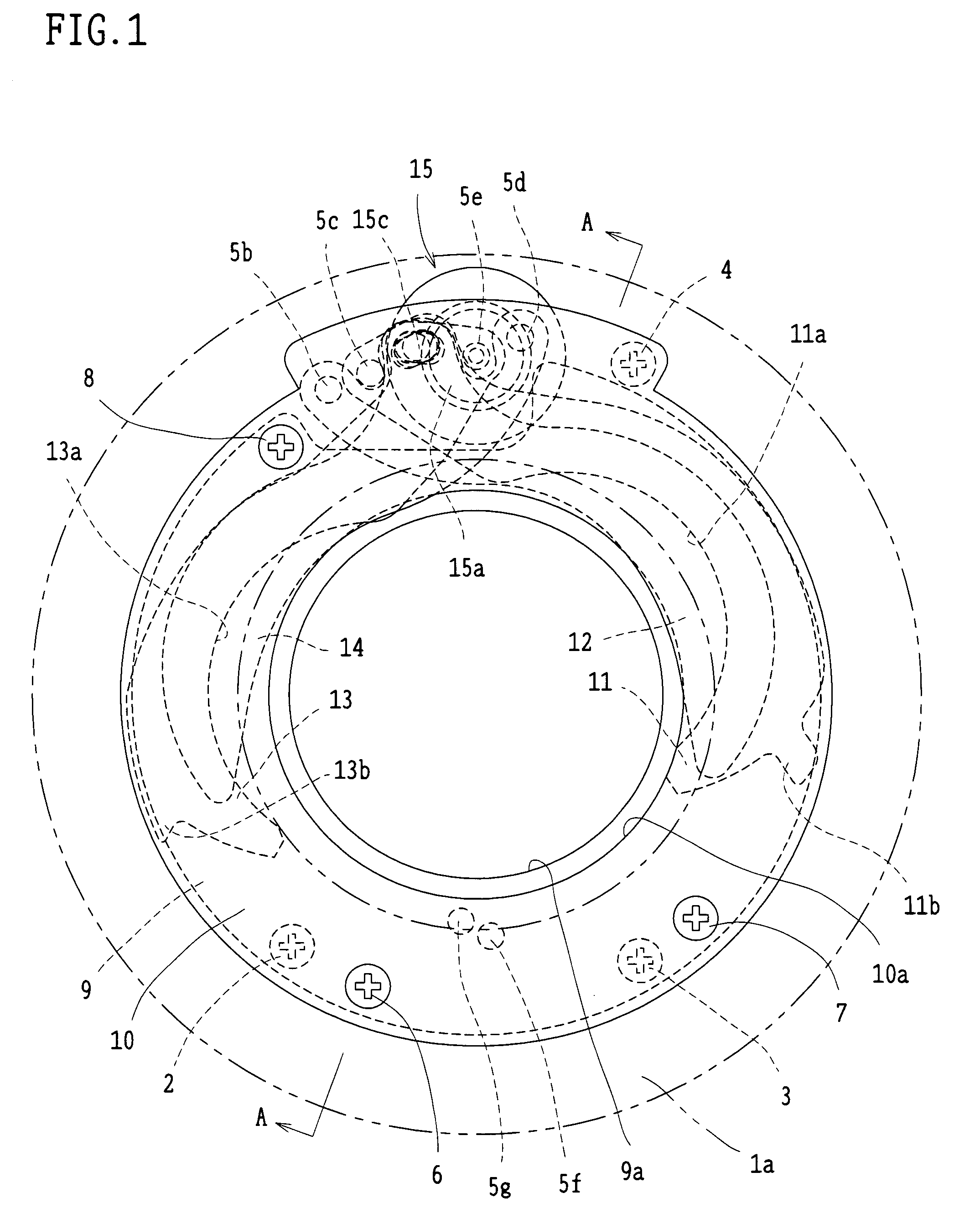
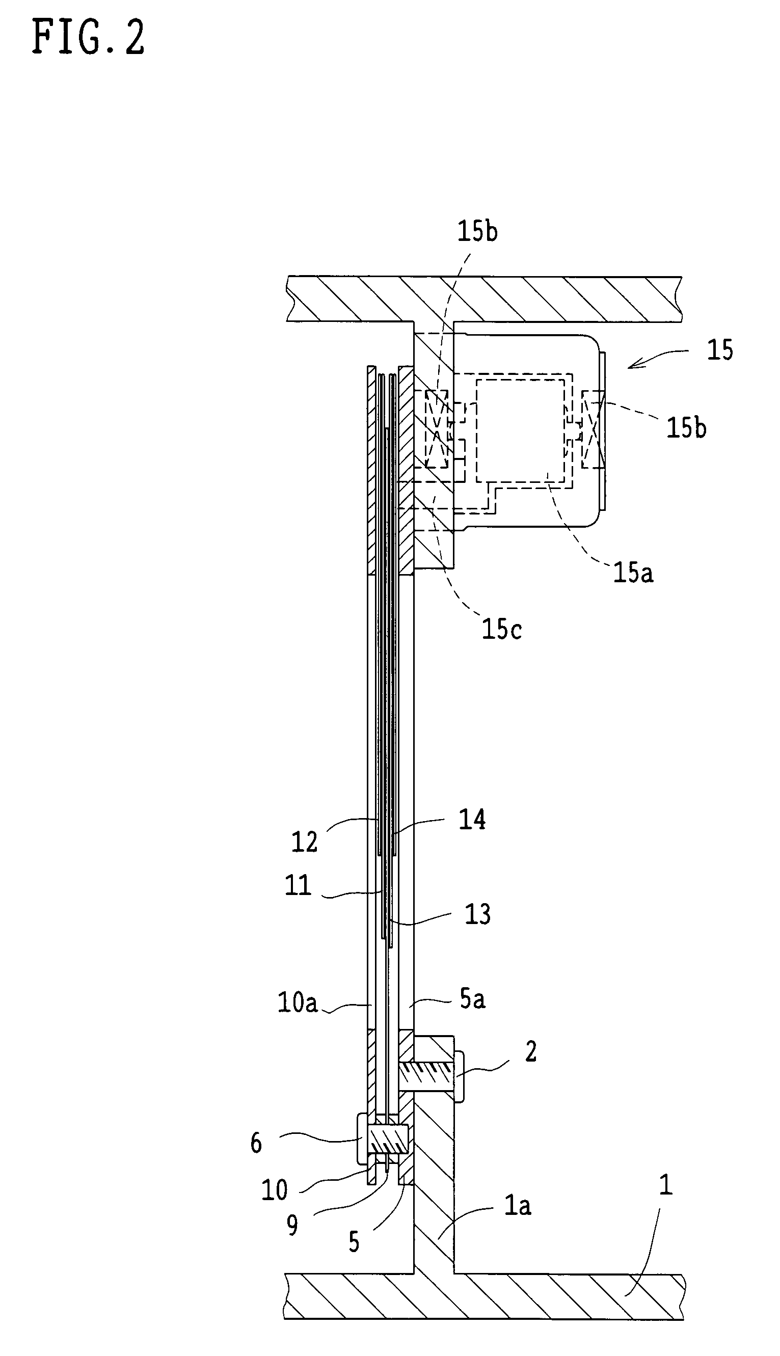
[0021]A diaphragm device according to the present embodiment is constructed so as to be easily installed in a lens frame (lens barrel) disposed in the vicinity of a light source. More specifically, a lens frame 1 shown in FIG. 2 is cylindrically shaped and has an annularly projecting mounting portion 1a therein. Referring to FIG. 1, the inner edge and the outer edge of the mounting portion 1a are indicated by double-dashed chain lines. The diaphragm device according to the present embodiment is constructed to be attached to the mounting portion 1a with three screws 2, 3 and 4.

[0022]As can be understood from FIG. 2, by three screws 6, 7 and 8 shown in FIG. 1, an intermediate plate 9 and a second base plate 10 are attached, in this order, to a first base plate 5 directly installed to the mounting portion 1a of the lens frame 1. An accommodating chamber is formed between the first base plate 5 and the intermediate plate 9, and another accommodating chamber is formed b...

second embodiment

[Second Embodiment]

[0035]Referring now to FIG. 4 through FIG. 6, the second embodiment will be explained. The construction of the present embodiment only partly differs from the construction of the first embodiment. Hence, the same reference numerals will be assigned to the same members and portions as those in the first embodiment, and the explanation thereof will be omitted. The operation of the present embodiment is entirely identical to that of the first embodiment, so that the description of the operation will be omitted. Thus, modification examples and advantages of the construction explained in the first embodiment will be directly applied also to the present embodiment.

[0036]An inner circumferential surface of an aperture 9a of an intermediate plate 9 in the present embodiment has a black finish rather than being provided with gray or white heat-resistant painting. In the case of the present embodiment also, a portion of the surface of the intermediate plate 9 that is adjace...


PUM


Abstract

A diaphragm device has a first base plate and a second base plate that are installed with a predetermined interval therebetween and formed into a unit. The diaphragm device is installed to a mounting portion of a lens frame such that the second base plate is disposed adjacently to a light source. The two base plates are partitioned with an intermediate plate to form two accommodating chambers, a stopping-down blade and a covering blade being disposed in each accommodating chamber. A motor is attached to the first base plate to relatively rotate a set of plate members and another set of plate members so as to restrict optical path apertures by the stopping-down blades. Portions directly exposed to light source light are provided with gray or white heat-resistant painting.

Description

BACKGROUND OF THE INVENTION[0001]1. Field of the Invention[0002]The present invention relates to a diaphragm device for light source light adjustment ideally disposed in the vicinity of a light source of a projecting apparatus, a projector, or the like.[0003]2. Description of the Related Art[0004]There has been known a projecting apparatus used for lighting on a stage or at a studio that has a diaphragm device disposed near a light source to restrict the projecting range or projecting configuration of light emitted from a light source (refer to Japanese Unexamined Patent Application Publication No. 7-99002). It is known that liquid crystal projectors and other various types of projectors have diaphragm devices disposed near light sources to temporarily change the quantity of lighting according to the brightness of projection room or to change projection images. Especially in the case of a liquid crystal projector, disposing such a diaphragm device is known to make it possible to res...

Claims


Application Information

Patent Timeline
IPC IPC(8): G03B9/02F21V11/18G02B5/00G03B9/06
CPCF21V11/18G02B5/005
Inventor SEITA, MASATO
Owner COPAL CO LTD
Why Eureka
Try Eureka