Selectively stiff FDB bearing for better servo write

a servo and bearing technology, applied in the field of disk drives, can solve the problems of increasing bearing stiffness, and achieve the effect of increasing the stiffness of the fdb bearing

Inactive Publication Date: 2005-12-13
SEAGATE TECH LLC
View PDF6 Cites 6 Cited by
  • Summary
  • Abstract
  • Description
  • Claims
  • Application Information

AI Technical Summary

Benefits of technology

[0011]The invention comprises selectively increasing the stiffness

Problems solved by technology

This reduction in temperature increases the viscosity o

Method used


Image

  • Selectively stiff FDB bearing for better servo write
  • Selectively stiff FDB bearing for better servo write
  • Selectively stiff FDB bearing for better servo write

Examples


Embodiment Construction

[0023]The disk drives and FDB motors shown and described in connection with figures are set forth only with sufficient detail necessary to understand the invention.

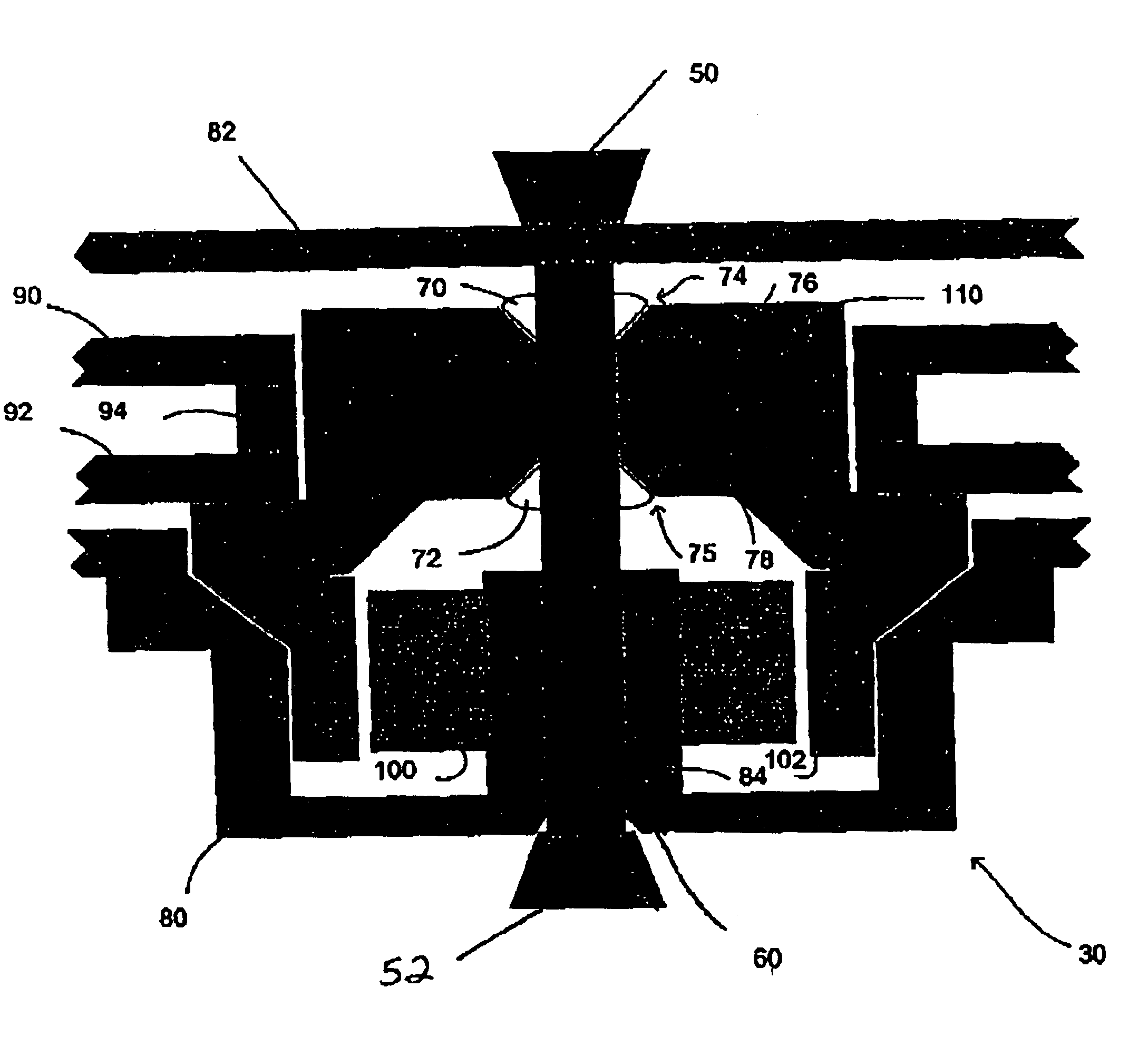
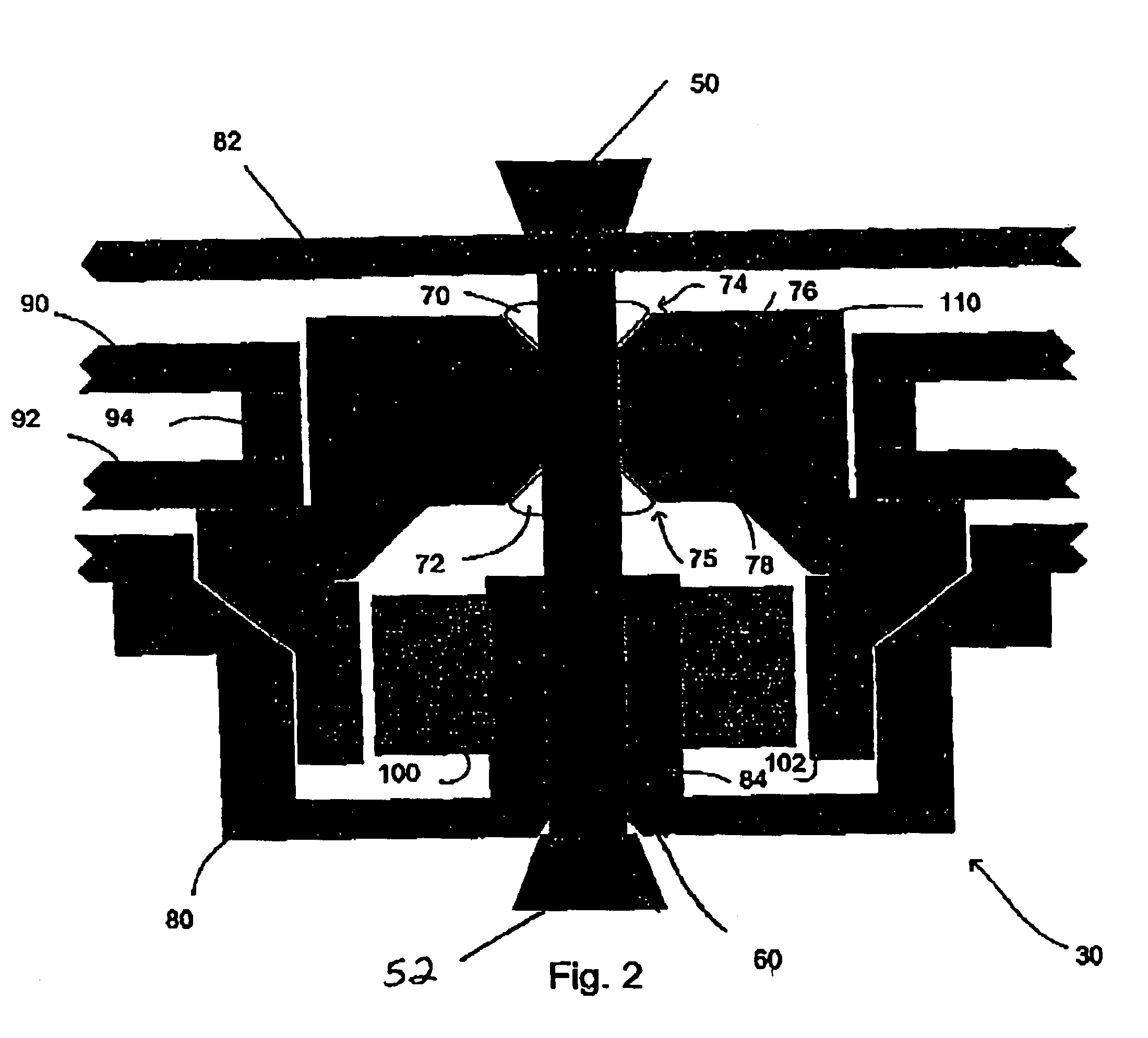
[0024]Referring to FIG. 2, disk drive 30 is shown mounted in a servo writer (most of whose structure is omitted for sake of clarity) by means of a clamp 50 and 52. Clamp members 50 and 52 abut the disk drive 30 at both ends of the FDB motor's 40 fixed shaft 60.

[0025]The FDB motor 40 is of the conical variety. It includes a fixed shaft 60 (typically stainless steel) interference mounted into a boss 84 of a base casting 80 (sheet metal) of the disk drive 30. The other end of the shaft 60 is affixed, typically by a screw (not shown) to the top cover 82 (sheet metal) of the disk drive casing. The FDB motor 40 further includes hub 110 (stainless steel) rotably mounted on the shaft by means of conical bearings 70 and 72. The conical bearings 70 and 72 are typically fixedly mounted on shaft 60. The interface between bearings 70 ...


PUM


Abstract

Hard disk drive track density is increased by selectively increasing the stiffness of a fluid dynamic bearing (FDB) motor during servo write. Applying a load to the shaft of a fixed shaft FDB motor to close the bearing gaps increases stiffness. Alternatively, the disk drive is cooled to increase bearing fluid viscosity or the motor is operated at an increased rotational velocity.

Description

CROSS-REFERENCE TO RELATED APPLICATIONS[0001]This application claims benefit of U.S. provisional patent application Ser. No. 60 / 338,412, filed on Dec. 5, 2001, which is herein incorporated by reference.BACKGROUND OF THE INVENTION[0002]1. Field of the Invention[0003]The invention relates to field of disk drives and more particularly to the writing of servo tracks onto the disks during manufacture.[0004]2. Description of the Related Art[0005]Disk drive servo tracks are typically written onto a blank magnetic disk after the disk drive has been substantially assembled. While there are many known methods for writing servo tracks onto a blank magnetic disk, the most common methods include the use of a laser interferometer to control a picker that attaches to the ARM assembly of the disk drive and steps the arms and the heads, attached to the end of the arms, across the disk while writing the servo patterns.[0006]In a mechanically perfect world, servo tracks would be written in perfectly c...

Claims


Application Information

Patent Timeline
IPC IPC(8): F16C17/10F16C33/10G11B19/20
CPCF16C17/10F16C33/107G11B19/2009F16C2370/12
Inventor HERNDON, TROY MICHAELPARSONEAULT, NORBERT STEVENMACLEOD, DONALD JAMES
Owner SEAGATE TECH LLC
Why Eureka
Try Eureka