Receiver

Inactive Publication Date: 2005-12-13
JVC KENWOOD CORP A CORP OF JAPAN
View PDF20 Cites 24 Cited by
  • Summary
  • Abstract
  • Description
  • Claims
  • Application Information

AI Technical Summary

Benefits of technology

[0064]The phase error data corresponding to the I and Q symbol stream data after the absolute phasing by the inverse phase rotation means is read from the phase error table of the carrier reproduction means. Accordingly, irrespective of what value the reception signal phase rotation angle takes, the received signal point of the I and Q sym

Problems solved by technology

As the phase of the received signal point changes randomly relative to the transmission side, it is impossible to identify the received digital signal.
However, if it is pres

Method used


Image

  • Receiver
  • Receiver
  • Receiver

Examples


first embodiment

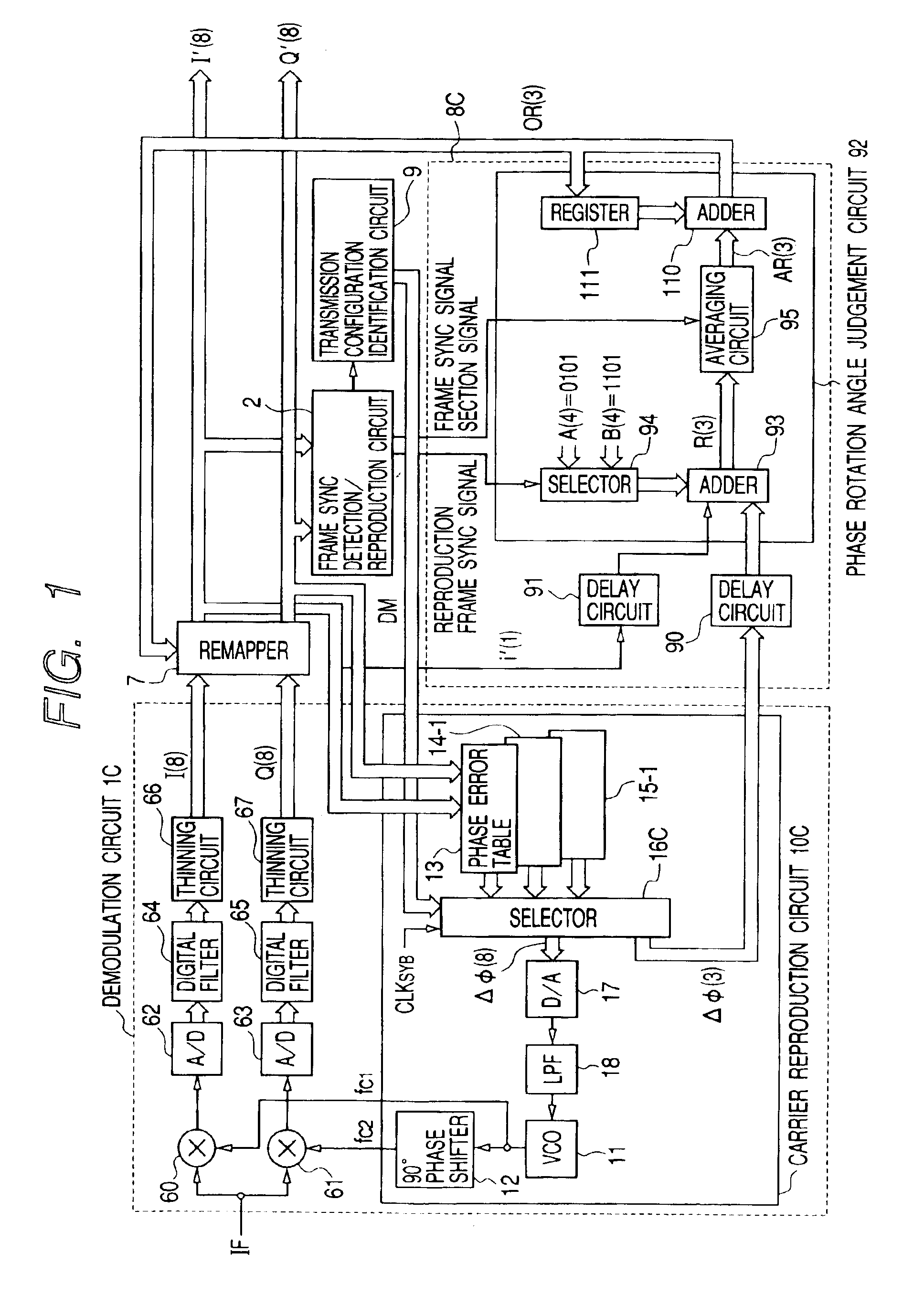
[0092]the invention will be described with reference to FIG. 1.

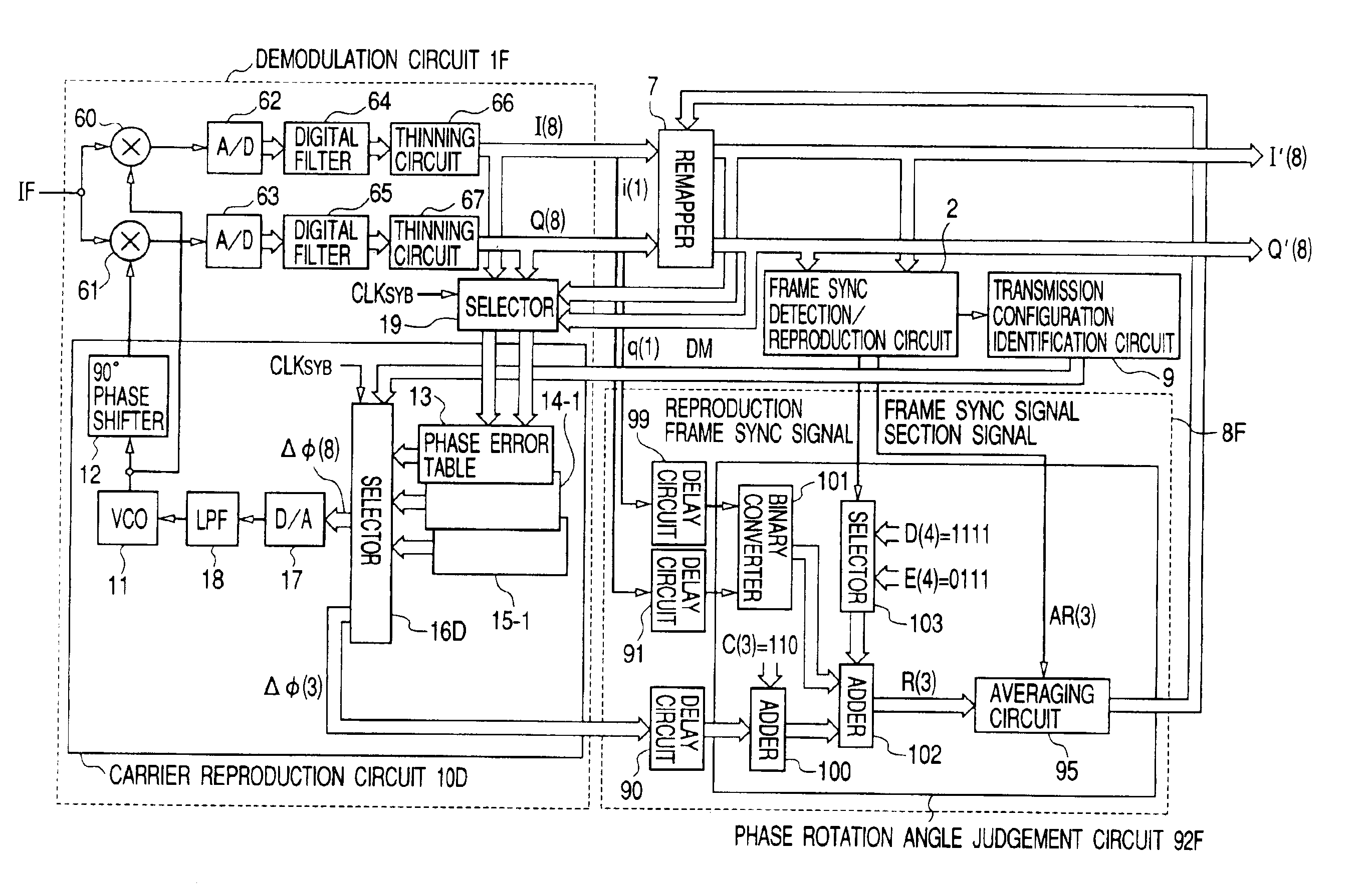
[0093]FIG. 1 is a block diagram showing the main portion of a broadcasting receiver (PSK modulated wave receiver) of this invention. FIG. 1, elements equivalent to those shown in FIG. 10 are represented by identical reference numerals.

[0094]In the receiver shown in FIG. 10, the carrier wave reproduction circuit has seven phase error tables 13, 14-1, 14-2, and 15-1 to 15-4, and the I and Q symbol stream data I(8) and Q(8) from the demodulation circuit are input to the phase error tables. In the receiver shown in FIG. 10, only three phase error tables 13, 14-1 and 15-1 are used, and the I and Q symbol stream data I′(8) and Q′(8) from the remapper 7 are input to the phase error tables. The remapper 7 outputs input data as it is without phase rotation of the I and Q symbol stream data I(8) and Q(8) output from the demodulation circuit, until the reception signal phase rotation angle detection circuit detects the phase rotati...

second embodiment

[0126]Next, the invention will be described with reference to FIG. 5.

[0127]FIG. 5 is a block diagram showing the main portion of a broadcasting receiver (PSK modulated wave receiver) of this invention. In FIG. 5, like elements to those shown in FIG. 1 are represented by using identical reference numerals.

[0128]In the embodiment shown in FIG. 1, the phase error data ΔΦ(3) is read from the BPSK phase error table 15-1, whereas in the embodiment shown in FIG. 5, the phase error data ΔΦ(3) is read from the QPSK phase error table 14-1 (refer to FIG. 16).

[0129]After the reception start and until the transmission configuration identification circuit 9 identifies the multiplex configuration of the frame and a reception signal phase rotation angle detection circuit 8D detects the reception signal phase rotation angle, a selector 16D of a carrier reproduction circuit 10D enables only the 8PSK phase error table 13 during the period while the symbol clock CLKSYB takes the high level, reads the p...


PUM


Abstract

When reception of multiplexed PSK modulated waves BPSK and 8PSK starts, a selector (16C) of a demodulation circuit (IC) read higher-order three bits ΔΦ(3) of the phase error data corresponding to outputs I′ and Q′ of a remapper (7) for performing absolute phasing from a phase error table for BPSK out of tables provided for respective types of modulation methods. A reception signal phase rotation angle detection circuit (8C) detects the phase rotation angle corresponding to a bit “1” of a frame sync signal of a received symbol stream from ΔΦ(3) and the MSB of the output I′ of the remapper (7) and outputs the phase rotation angle to the remapper (7) to allow the remapper (7) to perform absolute phasing. The selector (16C) reads phase error data corresponding to the received symbol data after absolute phasing output from the remapper (7) from the phase error table corresponding to the modulating method identified by a transmission configuration identification circuit (9), outputs the phase error data to a D/A converter (17), corrects the phase of carrier waves for orthogonal detection, and causes the difference in phase between the received signal point and the transmission signal point to be constant.

Description

TECHNICAL FIELD[0001]The present invention relates to a receiver for receiving PSK modulated signals of digital signals which are modulated by a plurality of PSK modulation methods having different phase numbers such as two and eight phases, two and four phases, four and eight phases, or two and four and eight phases, particularly by hierarchical transmission methods, and which are multiplexed in time, and for demodulating the PSK modulated signals by using carriers reproduced by a carrier reproduction unit to output I and Q symbol stream data.BACKGROUND ART[0002]Digital satellite TV broadcasting by a hierarchical transmission method is being developed toward practical use in which digital waves modulated by a plurality of modulation methods having different necessary C / N values, such as 8PSK modulated waves, QPSK modulated waves, and BPSK modulated waves, are multiplexed in time and repetitively transmitted one frame after another.[0003]FIG. 9A is a diagram showing an example of th...

Claims


Application Information

Patent Timeline
IPC IPC(8): H04L27/227
CPCH04L27/2273
Inventor SHIRAISHI, KENICHI
Owner JVC KENWOOD CORP A CORP OF JAPAN
Why Eureka
Try Eureka