Sound collecting device minimizing electrical noise

a technology of sound collection and electrical noise, which is applied in the direction of electric apparatus casings/cabinets/drawers, domestic cooling apparatus, instruments, etc., and can solve problems such as shielding

Inactive Publication Date: 2005-12-13
PANASONIC CORP
View PDF19 Cites 11 Cited by
  • Summary
  • Abstract
  • Description
  • Claims
  • Application Information

AI Technical Summary

Benefits of technology

[0007]It is another object of the present invention to provide a sound collecting device designed to minimize adverse effects on an output caused by dust, frozen foreign substances lying on an electroacoustic transducer exposed to the air, or electromagnetic noises inputted directly to the transducer.
[0011]A temperature sensor is provided which measures an ambient temperature. The controller controls the vibrating circuit to vibrate the transducer at a shorter time interval when the ambient temperature measured by the temperature sensor is lower than a given value and at a longer time interval when the ambient temperature is higher than a given value.

Problems solved by technology

The transducer 2 is usually exposed to the air for catching sound waves and thus has the problems in that dust is gathered on a diaphragm of the transducer 2 with time or when the device is used in winter, it may cause the moisture in the air to be frozen solid on the diaphragm, which affects on an operation of the transducer 2, and in that since the transducer 2 needs to be exposed directly to the air, it is difficult to use a shield for protecting the transducer 2 from electromagnetic waves originating from high-voltage cables or transmission antennas, so that the electromagnetic noises are inputted directly to the transducer 2.

Method used


Image

  • Sound collecting device minimizing electrical noise
  • Sound collecting device minimizing electrical noise
  • Sound collecting device minimizing electrical noise

Examples


first embodiment

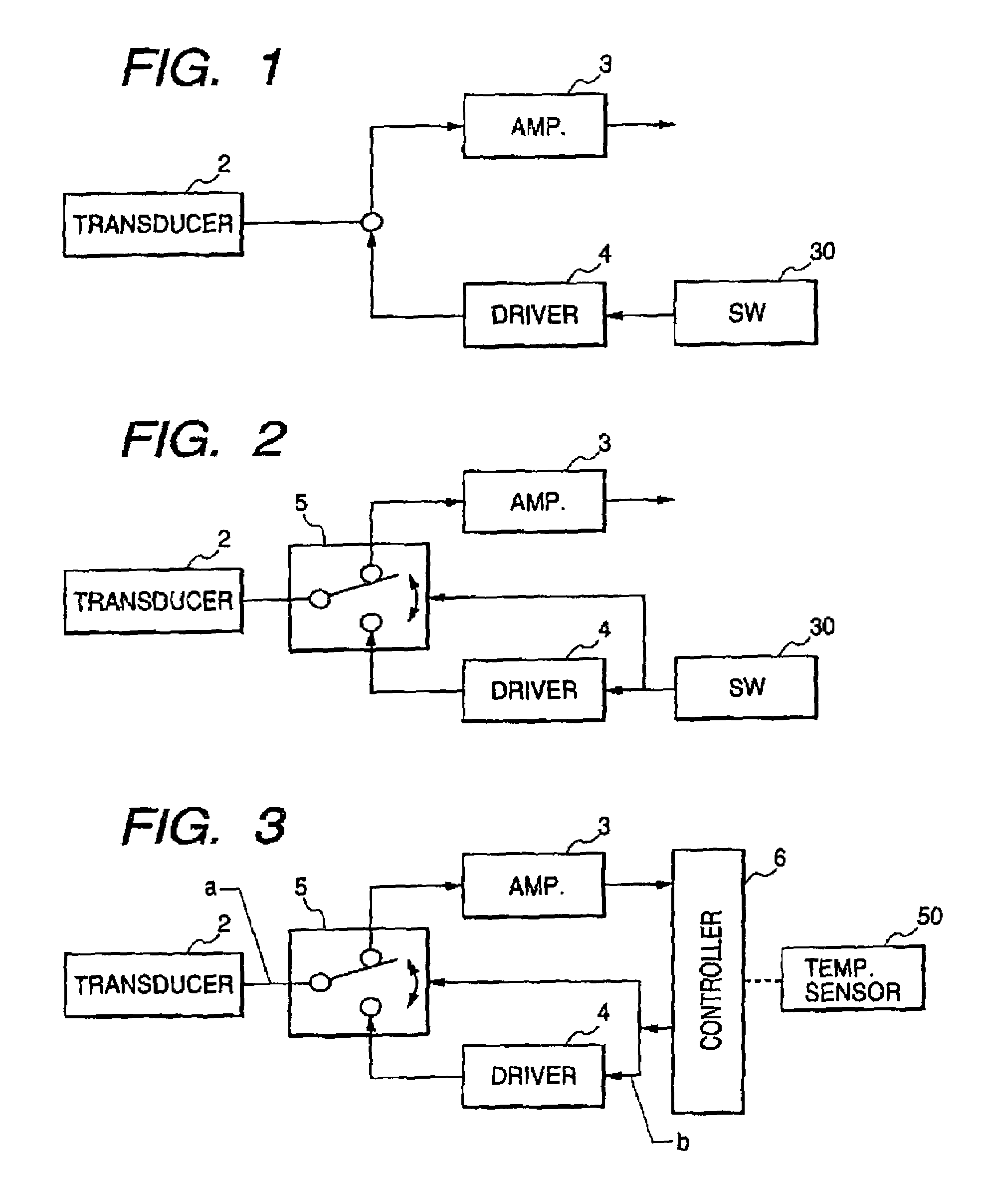
[0031]Referring now to the drawings, wherein like numbers refer to like parts in several views, particularly to FIG. 1, there is shown a sound collecting device according to the present invention. The sound collecting device generally includes an electroacoustic transducer 2 (e.g., a microphone), a preamplifier 3, a drive circuit 4, and a manual switch 30 and has substantially the same mechanical structure as that in the conventional one shown in FIG. 8. Specifically, the transducer 2 is installed in a base of a horn such as the one shown in FIG. 8 designed so as to increase in sectional area in a lengthwise direction for ease of collecting sound waves. The transducer 2 is responsive to the sound waves or sound-producing vibrations applied to, for example, a diaphragm to vibrate to produce corresponding electrical signals and outputs them to the preamplifier 3. The preamplifier 3 amplifies the input signals and outputs them to an external device (not shown). The drive circuit 4 is c...

fourth embodiment

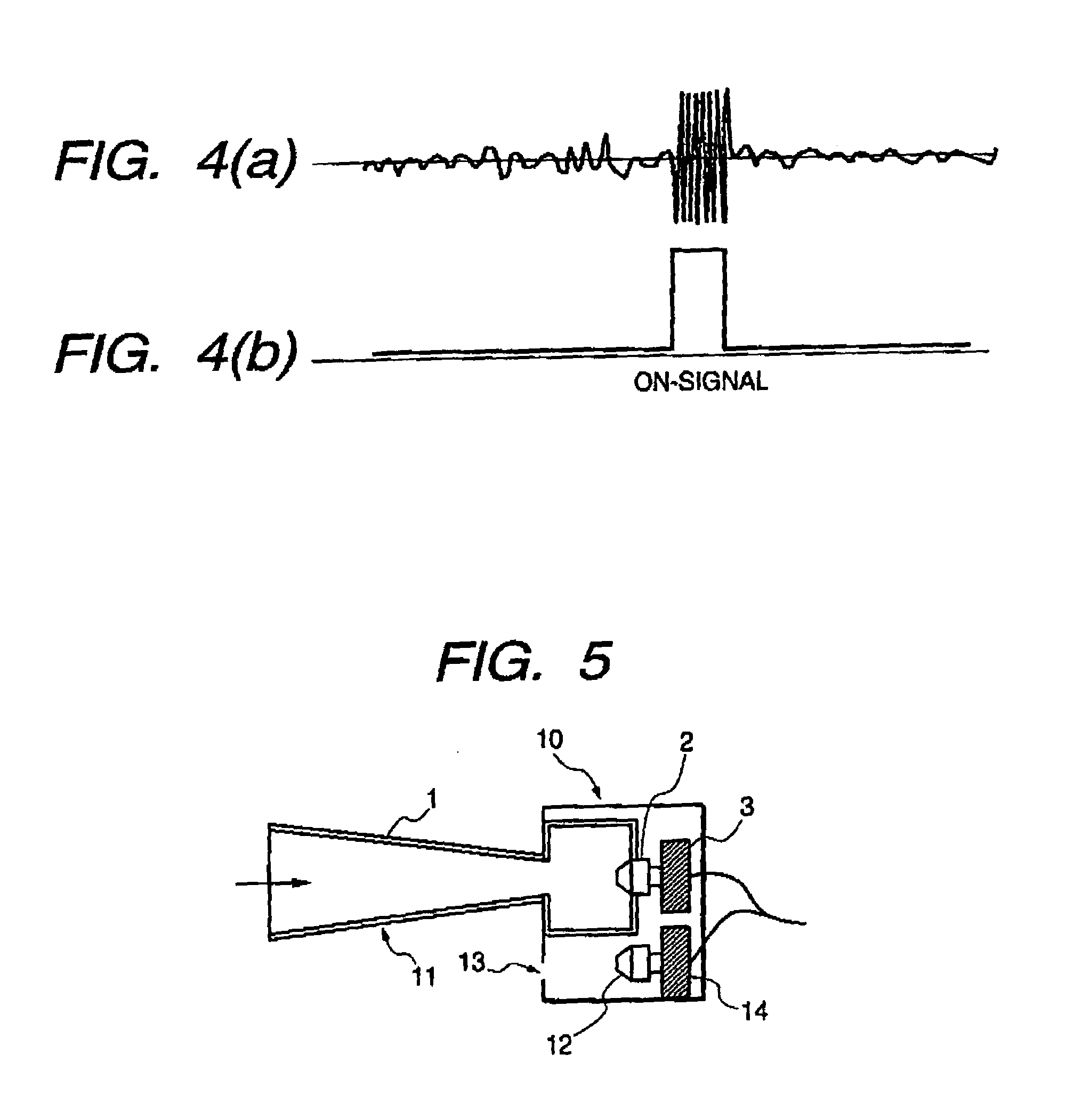
[0040]FIG. 5 shows a sound collecting device according to the invention.

[0041]The sound collecting device includes generally a housing 10 and a sound collecting unit 11 installed in the housing 10. The sound collecting unit 11 consists of a horn 1 designed so as to increase in sectional area in a lengthwise direction for ease of collecting the sound wave and an electroacoustic transducer 2 installed in a base of the horn 1. A preamplifier 3, like the above embodiments, connects electrically with the transducer 2.

[0042]The sound collecting device also includes an electromagnetic sensor 12, an amplifier 14, and a subtractor 15. The electromagnetic sensor 12 is made of a transducer and disposed in the housing 10 to catch electromagnetic waves (i.e., electric noises) inputted through an opening 13 and outputs a signal indicative thereof to the amplifier 14. The opening 13 is formed in the front surface of the housing 10 from which the horn 1 extends so that the electromagnetic sensor 12...


PUM


Abstract

A sound collecting device is provided which is designed to minimize adverse effects on an output caused by exposure of an electroacoustic transducer to the air. The device includes an electroacoustic transducer and a vibrating circuit. The transducer is exposed to the air and responsive to input of a sound wave to produce a corresponding acoustic signal. The vibrating circuit vibrates the transducer to shake foreign substances such as dust or drops of water from the transducer. In a modified form, an electromagnetic sensor is provided which measures an electromagnetic noise transmitted to the transducer and which removes the electromagnetic noise from an output of the transducer to produce a noiseless acoustic signal.

Description

BACKGROUND OF THE INVENTION[0001]1. Technical Field of the Invention[0002]The present invention relates generally to a sound collecting device designed to minimize electric noises caused by dust, frozen foreign substances lying on an electroacoustic transducer exposed to the air, or electromagnetic noises inputted directly to the transducer.[0003]2. Background Art[0004]FIG. 8 shows a conventional sound collecting device which consists of a horn 1 designed so as to increase in sectional area in a lengthwise direction for ease of collecting the sound wave, an electroacoustic transducer 2 (i.e., a microphone) installed in a base of the horn 1, and a preamplifier 3 connecting electrically with the transducer 2. An audio signal outputted from the transducer 2 is, as clearly shown in FIG. 9, amplified by the preamplifier 3 and outputted to an external device.[0005]The transducer 2 is usually exposed to the air for catching sound waves and thus has the problems in that dust is gathered on ...

Claims


Application Information

Patent Timeline
Patent Type & Authority Patents(United States)
IPC IPC(8): G10H3/14G10H3/18H04R1/08H04R3/00H04R23/00H04R23/02H04R25/00
CPCG10H3/14H04R1/086G10H2220/351
Inventor KINOSHITA, HIDETOSHI
Owner PANASONIC CORP
Why Eureka
Try Eureka