
Outdoor sign support system

a technology for supporting systems and signs, applied in the direction of machine supports, building scaffolds, domestic objects, etc., can solve problems such as accidental detachment of signs from posts

Inactive Publication Date: 2005-12-20
SIGNALISATION KALITEC
View PDF44 Cites 39 Cited by
  • Summary
  • Abstract
  • Description
  • Claims
  • Application Information

AI Technical Summary

Benefits of technology

"The present invention provides a new outdoor sign mounting system that offers flexibility in installation while still being of sturdy construction. The system includes an elongated channel member that is mounted on the backside of a sign, a bracket that is mounted to a post, and a collar that is tightly surround the post. The bracket has a channel engaging portion that is slidably engaged into the channel member on the backside of the sign. The collar has at least two rail engaging members that are located on the outer surface of the post, and a rail that is slidably engageable with the selected rail engaging member. The system also includes an elongated rail that is mounted on the rear surface of the sign, and a bracket that is mounted to an outdoor post. The bracket has a rail engaging portion that is slidably engaged with the rail, and once the position of the sign relative to the post has been adjusted, further sliding movement between the rail engaging member and the rail is prevented by tightening a threaded fastener extending internally of the bracket against the outdoor post."

Problems solved by technology

Although the above described attachment system provides flexibility in the adjustment of the position of the sign on the post, it has been found that the strip may become loose overtime, which may result in accidental detachment of the sign from the post.

Method used


Image

  • Outdoor sign support system
  • Outdoor sign support system
  • Outdoor sign support system

Examples


Embodiment Construction

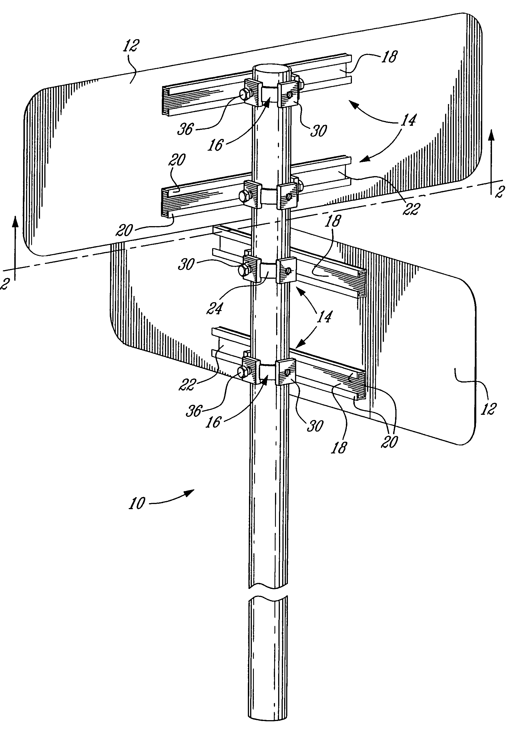
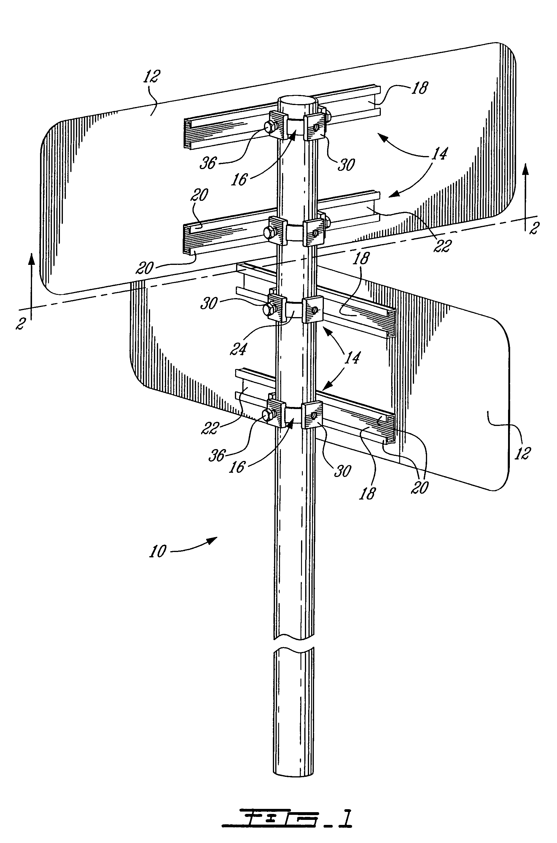
[0014]FIG. 1 illustrates an outdoor post 10 carrying two road signs 12. According to the present invention, the signs 12 are releasably secured in position on the post 10 by means of channel and collar assemblies 14.

[0015]Each channel and collar assembly 14 generally comprises a bracket preferably in the form of a one piece endless collar 16 and an elongated channel member 18 or rail. The channel member 18 is preferably adhesively secured to the rear side of the sign to be mounted on the post 10. The channel member 18 is preferably provided in the form of an aluminum extrusion and comprises a pair of inturned lips 20 defining a mouth 22 therebetween. The channel member 18 has the advantage of reinforcing the sign 12.

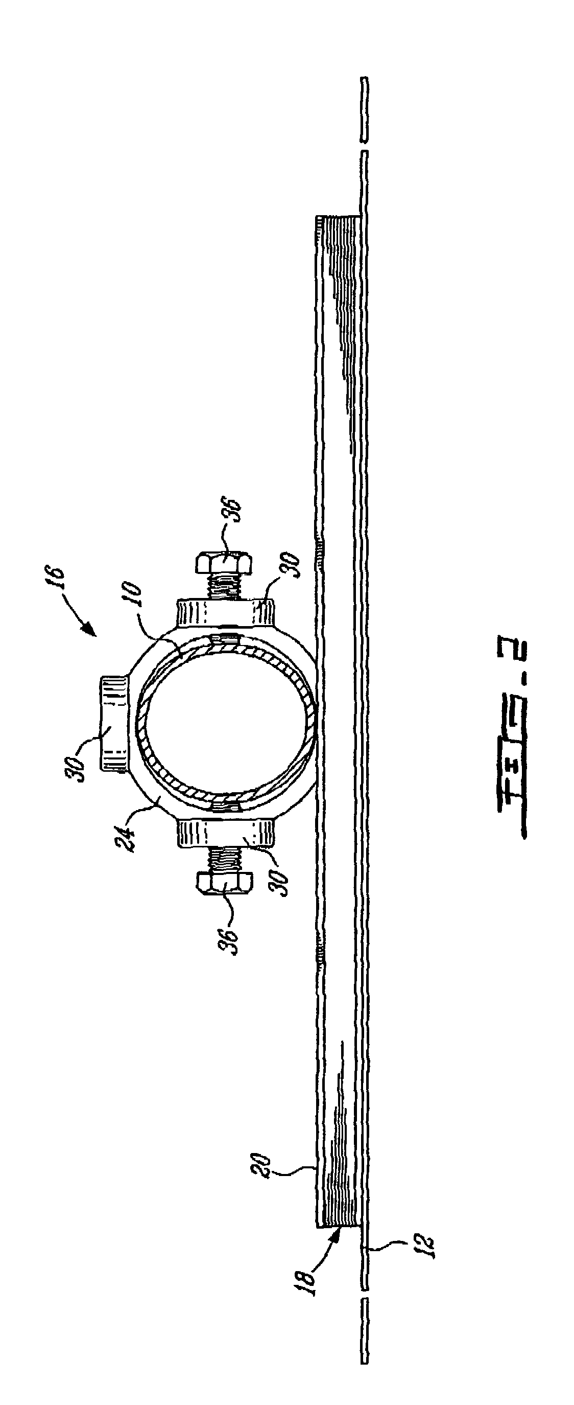
[0016]As shown in FIG. 3, each collar 16 comprises a continuous annular band 24 defining a closed space generally corresponding to the outline of the post 10 on which the collar 16 is to be fitted over. According to the illustrated embodiment, the post and the band are e...


PUM


Abstract

A system for mounting a sign to a post comprises an elongated channel member adapted to be mounted on a backside of a sign and a bracket adapted to be mounted to a post to which the sign is to be mounted. The bracket has a channel engaging portion adapted to be slidably engaged into the channel member on the backside of the sign. The bracket comprises an endless collar extending along a continuous closed line and adapted to be fitted over the post. The collar defines at least one transversally oriented hole in which a threaded fastener is threadably engaged with a leading end thereof projecting inwardly of the continuous endless collar for exerting a pushing action on the post in order to secure the collar on the post while at the same time drawing the channel member against the post so as to prevent relative movement between the sign and the bracket.

Description

BACKGROUND OF THE INVENTION[0001]1. Field of the Invention[0002]The present invention relates to a system suitable for mounting a sign or the like, to an outdoor post.[0003]2. Description of the Prior Art[0004]U.S. Pat. No. 4,211,381 issued on Jul. 8, 1980 to Heard discloses a device for mounting a sign to a post. The mounting device comprises a channel member mounted on the backside of the sign and a plastically deformable stainless steel strip. The channel member comprises a pair of inturned lips defining therebetween a mouth. The strip comprises an elongated plate adapted to be slidably engaged in the channel member behind the inturned lips. The free ends of the strip are turned outwardly to provide a pair of mutually facing flanges. The flanges define a paid of holes aligned along a direction tangential to the post. The flanges are secured together by a bolt and a nut. By tightening the bolt, the strip is plastically deformed in tight engagement about the post. This causes the e...

Claims


Application Information

Patent Timeline
Patent Type & Authority Patents(United States)
IPC IPC(8): A47B96/06A47K1/00G09F7/18G09F7/20G09F15/00
CPCG09F7/18G09F2007/1804G09F2007/1817G09F2007/1826
Inventor LAPOINTE, JEANGRIFFITH, ROBERT
Owner SIGNALISATION KALITEC
Learn More