
Carousel devices

a technology of carousel and device, which is applied in the field of carousel devices, can solve the problems of little innovation, unaddressed areas, and unimaginative bouncers for toddlers, and achieve the effects of enhancing the enjoyment of the device, significant stability, and alarming obesity ra

Inactive Publication Date: 2005-12-20
CLARKE WILLIAM A +1
View PDF8 Cites 14 Cited by
  • Summary
  • Abstract
  • Description
  • Claims
  • Application Information

AI Technical Summary

Benefits of technology

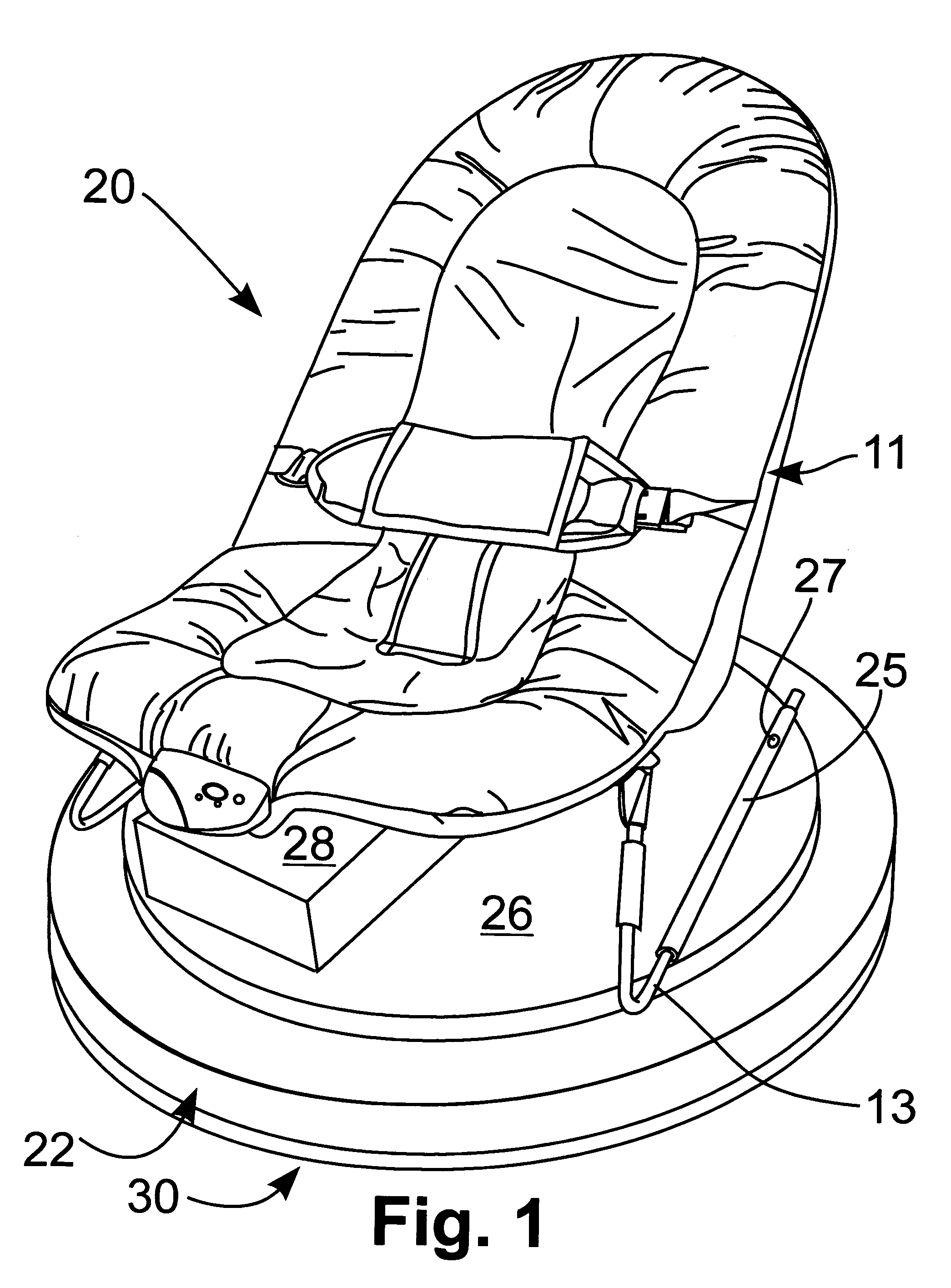
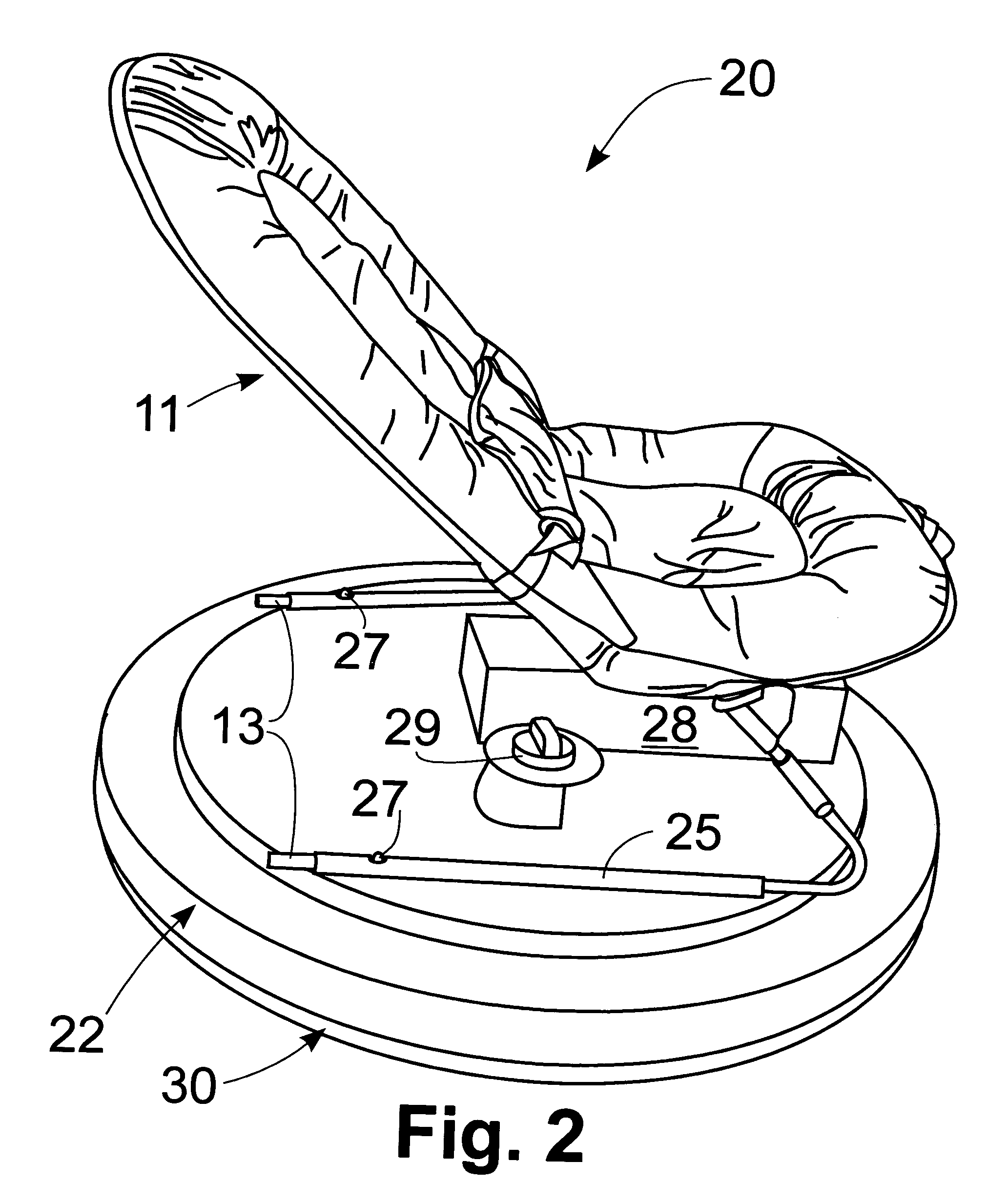
"The present invention is about carousel devices for toddlers and young children. The first invention provides a stable bouncer on the carousel base and rockers for added movement. The bouncer has an oscillation circuit that can induce sleep in the toddler. The second embodiment is a self-driven carousel riding toy with pedals and a sound generator to encourage the child to keep pedaling. The rotational base is supported by a ball-bearing race for more rotation with less resistance. The invention provides innovation and stability for carousel devices and promotes physical exercise for children."

Problems solved by technology

While these patented devices are significant advances in the areas they address, several areas remain unaddressed.
First, bouncers for toddlers are routinely unimaginative; very little innovation has taken place in this area.
In addition, the flimsy bouncers in use today, are at risk to tip over possibly injuring the baby.
Second, all carousel devices heretofore have been powered by an electric motor.
With increased time spent viewing television, videos, computer screens, and reduced emphasis on physical education in the school system, many children fail to get adequate exercise for proper muscle development, let alone, for avoiding becoming overweight.

Method used


Image

  • Carousel devices
  • Carousel devices
  • Carousel devices

Examples


second embodiment

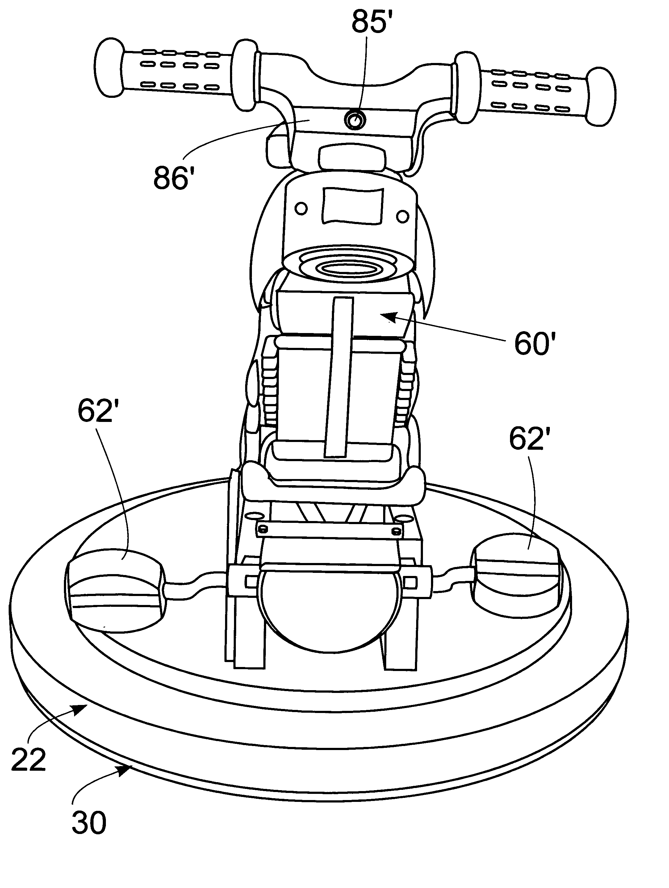
[0023]the carousel device of the present invention is depicted in FIGS. 7 and 8 generally at 20′. In this embodiment a straddlable vehicle 60′, shown here as a motorcycle, is fixedly mounted on rotational base 22′. Pedals 62′ are provided to enable the youngster to provide her / his own motivation. As seen in FIGS. 9A and 9B, the pedals can be connected to the rotational base 22′ through either a belt drive system 64′ or a chain drive system 74′. The belt drive system includes a pulley 66′ with a central V 67′ to facilitate tracking of belt 68′. Belt 68′ also is wrapped around driven means, a large diameter pulley 70′, which is attached to the underside of rotational base 22′. Chain drive 74′ includes a first gear 76′ and a second gear 77′ about which chain 78′ travels. On shaft 79′ which mounts gear 77′, a spiral gear 80′ is fixedly mounted and engages driven means, a second spiral gear 82′, which is non-rotationally attached to a pulley 70″ or may be directly attached to rotational ...

first embodiment

[0026]Various changes, alternatives and modifications will become apparent to one of ordinary skill in the art following a reading of the foregoing specification. For example, although the means for performing the oscillation of the first embodiment is preferred to be an electronic circuit, it will be appreciated a crank arm or other mechanical means, could be utilized instead without departing from the scope of the invention. Further, although the prototype shows wires interconnecting system components, in the production circuit board components will normally be soldered together. It is intended that any such changes, alternatives and modifications as fall within the scope of the appended claims be considered part of the present invention.


PUM


Abstract

A first embodiment of carousel device provides a bouncer which cannot be tipped over accidentally. Further, a oscillating circuit enables a battery-operated motor to gently oscillate the bouncer through an 80° arc. A pair of retractable rockers are provided on the bottom of the stationary base to afford the baby additional motion while bouncing. A second embodiment provides a straddlable vehicle which a youngster can peddle, a sound circuit being activated by the pedaling as inducement to continue exercising.

Description

[0001]This is a divisional application based on U.S. patent application Ser. No. 10 / 863,049 filed Jun. 7, 2004 now U.S. Pat. No. 6,869,368.BACKGROUND AND SUMMARY OF THE INVENTION[0002]The present invention relates to carousel devices. More particularly, the present invention is directed to oscillating and self-propelled amusement devices for toddlers and young children.[0003]One of the joint inventors hereof has developed a series of patented carousel devices including the Baby Carousel (U.S. Pat. No. 5,487,705 and D362,346), improvements thereto entitled Carousel Device (U.S. Pat. No. 5,660,430), Carousel Pony (U.S. Pat. No. 5,935,010) and Low-Profile Infant Swing Assembly (U.S. Pat. No. 6,343,994), each of which is hereby incorporated by reference. While these patented devices are significant advances in the areas they address, several areas remain unaddressed.[0004]First, bouncers for toddlers are routinely unimaginative; very little innovation has taken place in this area. In ad...

Claims


Application Information

Patent Timeline
Patent Type & Authority Patents(United States)
IPC IPC(8): A47D15/00A63G1/00
CPCA47D9/02A63G1/00A47D13/107A47D9/016A47D1/10A47D9/057
Inventor CLARKE, WILLIAM ACLARKE, PAMELA J.
Owner CLARKE WILLIAM A
Learn More