

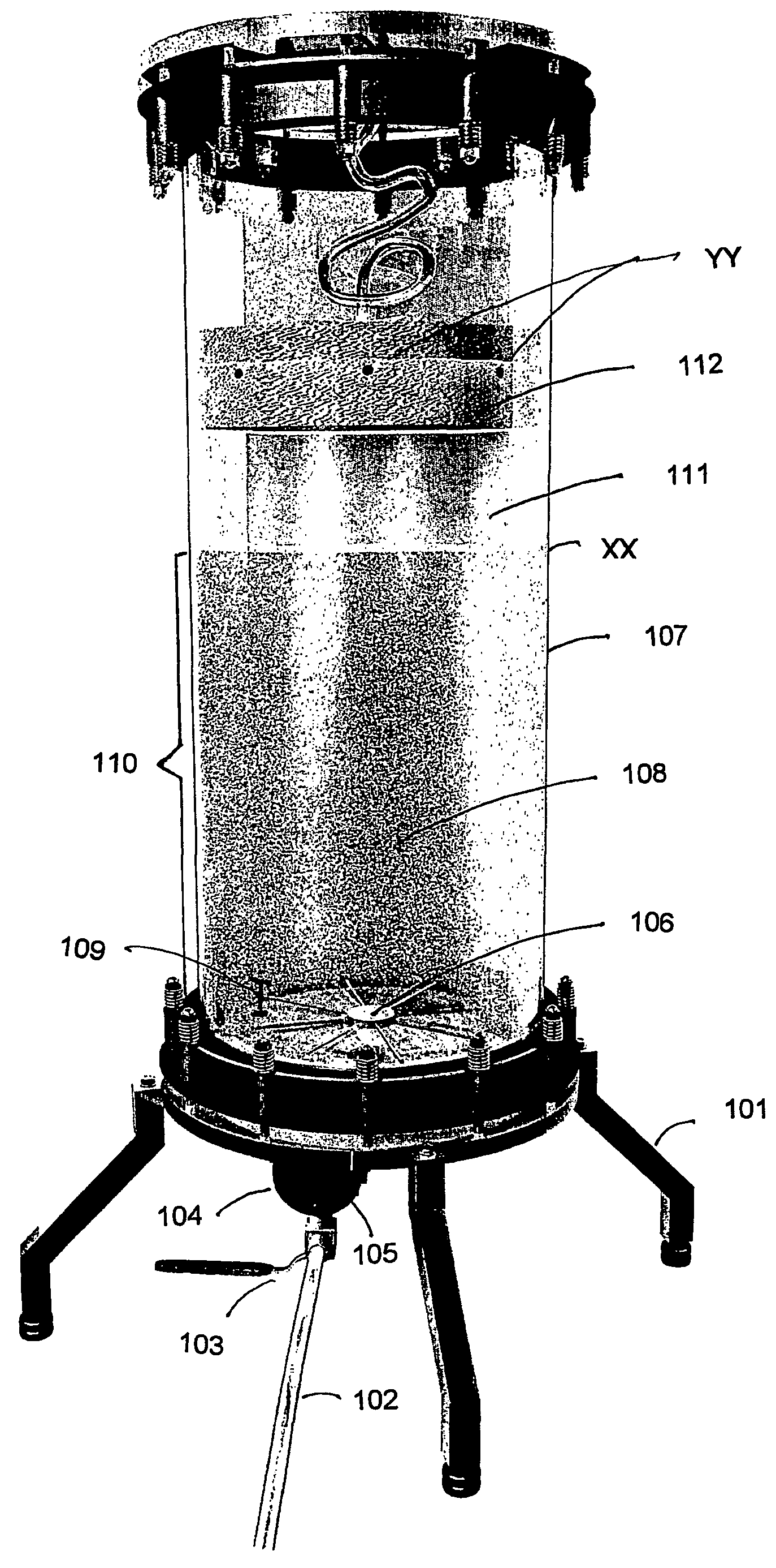
Bed adsorption system
a technology of adsorption system and bed, which is applied in the direction of cation exchanger, water/sludge/sewage treatment, biochemistry apparatus, etc., can solve the problems of fluid stream formation of channels in the bed, blockage of distribution plates, and clogging of particulate matter
- Summary
- Abstract
- Description
- Claims
- Application Information
AI Technical Summary
Benefits of technology
Problems solved by technology
Method used
Image

Examples
example 1
[0116]The following example illustrates the effect of using a rotating distributor as described above, comprising an arrangement of hollow steel tubes fitted with fluid outlet holes in an EBA column having a diameter of 150 cm. In this example the effect of flow rate on bed expansion is demonstrated.
Procedure
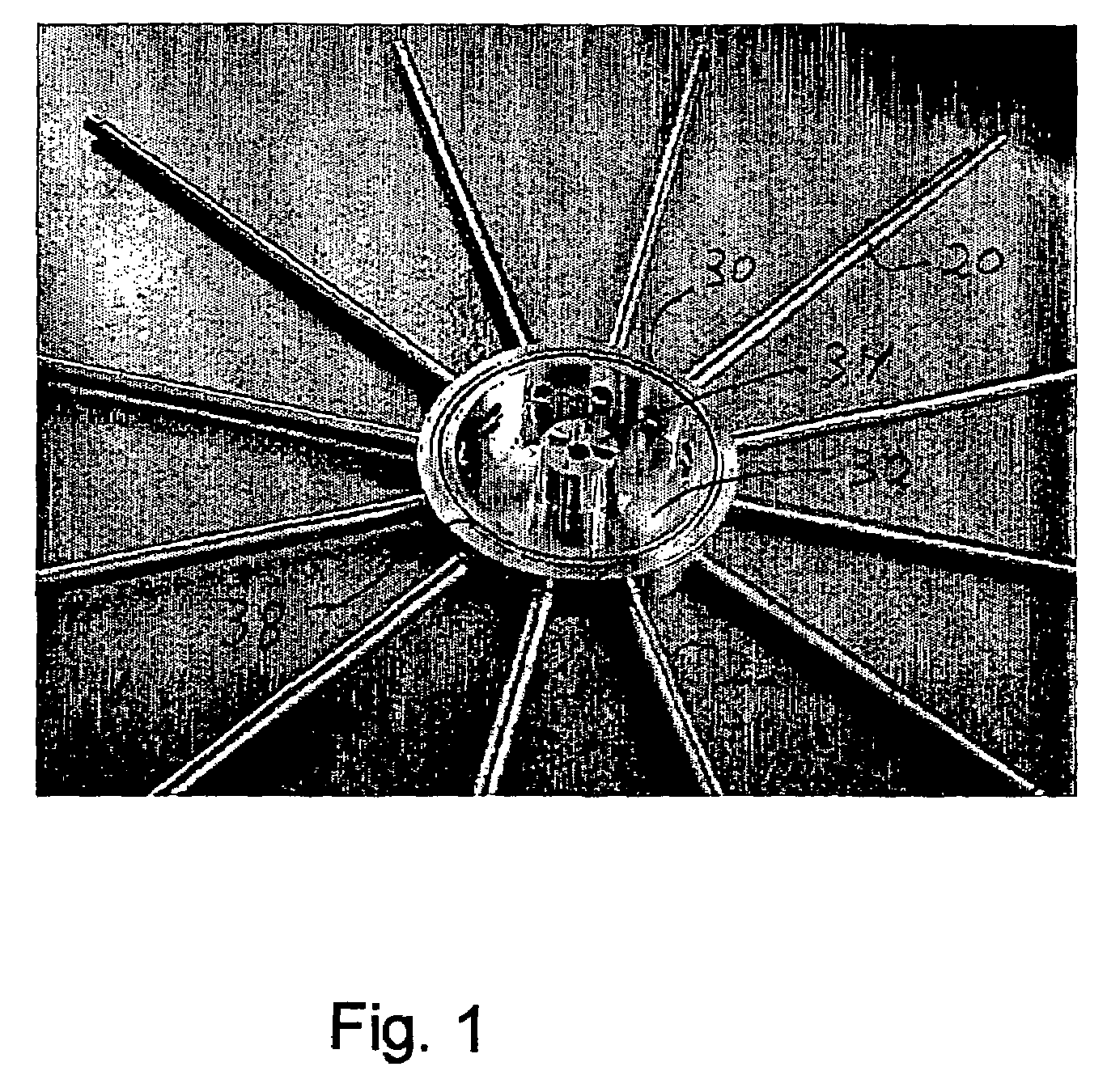
[0117]The rotating fluid distributor system described above was fitted to the EBA column by using bolts in the threaded holes (44: see FIG. 6) to fix the intermediate part (see FIG. 7a) onto the stainless steel base plate. The EBA column itself was specially constructed using a transparent material—PVC—so that the performance of the distributor could be monitored visually. The PVC column contained no internal protrusions, furthermore the base plate of the column was completely flat as can be seen in FIG. 6 and FIG. 7. The EBA column containing the distributor was initially filled with a suspension of a solid phase medium in water. The solid phase medium was a non-derivatised aga...
example 2
[0121]The rotating distributor and the column with solid phase medium as described in example 1 was further tested for generation of a stable expanded bed by examining the effect of distributor rotation rate on bed expansion.
[0122]The bed was fluidised as described in example 1 and then the expanded bed height was measured at different combinations of flow rate and distributor rotation rate. The bed expansion factor was then calculated as the ratio of expanded bed height to settled bed height. When the distributor was not rotated, bed expansion was poor (FIG. 28) demonstrating that rotation of the distributor is required to give the best bed expansion. No significant changes in the degree of expansion where observed by using a distributor rotation rate of 2.5 rpm to 10 RPM (FIG. 28). The result suggests that even fluid distribution was provided by the distributor when rotated at a wide range of rates and suggests a large window of operation is possible. Adequate and stable bed expan...
example 3
[0123]The rotating distributor and the column with solid phase medium as described in example 1 was further tested to examine the flow resulting in the column by visualising fluid flow via the use of dye tracers.
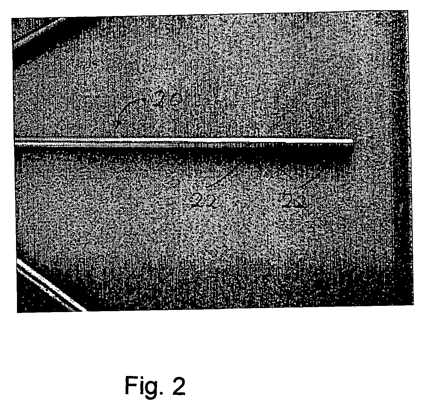
[0124]The bed was fluidised as described in example 1 at a volumetric flow rate of 5000 L / h and the distributor was rotated at 2.5 rpm. Using procedures commonly known to those involved in the art of expanded bed adsorption, a volume of 200 ml of a solution of freshly prepared bromophenol blue (10 g / L in 1 M NaOH) was prepared and then added to the column through a sample loop whilst the bed was fluidised with tap water at a flow rate of 5000 L / h. The location of dye near the column wall was then documented by taking photographs. It was observed that when dye first entered the column, a jet of dye penetrated to the corner of the wall and base plate (FIG. 29a) demonstrating that the fluid coming out of the outlet holes of the distributor was successfully directed downwards an...
PUM
| Property | Measurement | Unit |
|---|---|---|
| time lag | aaaaa | aaaaa |
| time lag | aaaaa | aaaaa |
| time lag | aaaaa | aaaaa |
Abstract
Description
Claims
Application Information