RF signal peak detector

a detector and signal technology, applied in the field of communication systems, can solve problems such as the less accurate peak detection circui

Inactive Publication Date: 2005-12-20
QUALCOMM INC
View PDF7 Cites 16 Cited by
  • Summary
  • Abstract
  • Description
  • Claims
  • Application Information

AI Technical Summary

Problems solved by technology

Still further, as the rate of the signal increases (e.g., into the Giga Hertz range), peak detection circuits become less accurate due to the speed and / or become more complex.

Method used


Image

  • RF signal peak detector
  • RF signal peak detector
  • RF signal peak detector

Examples


Embodiment Construction

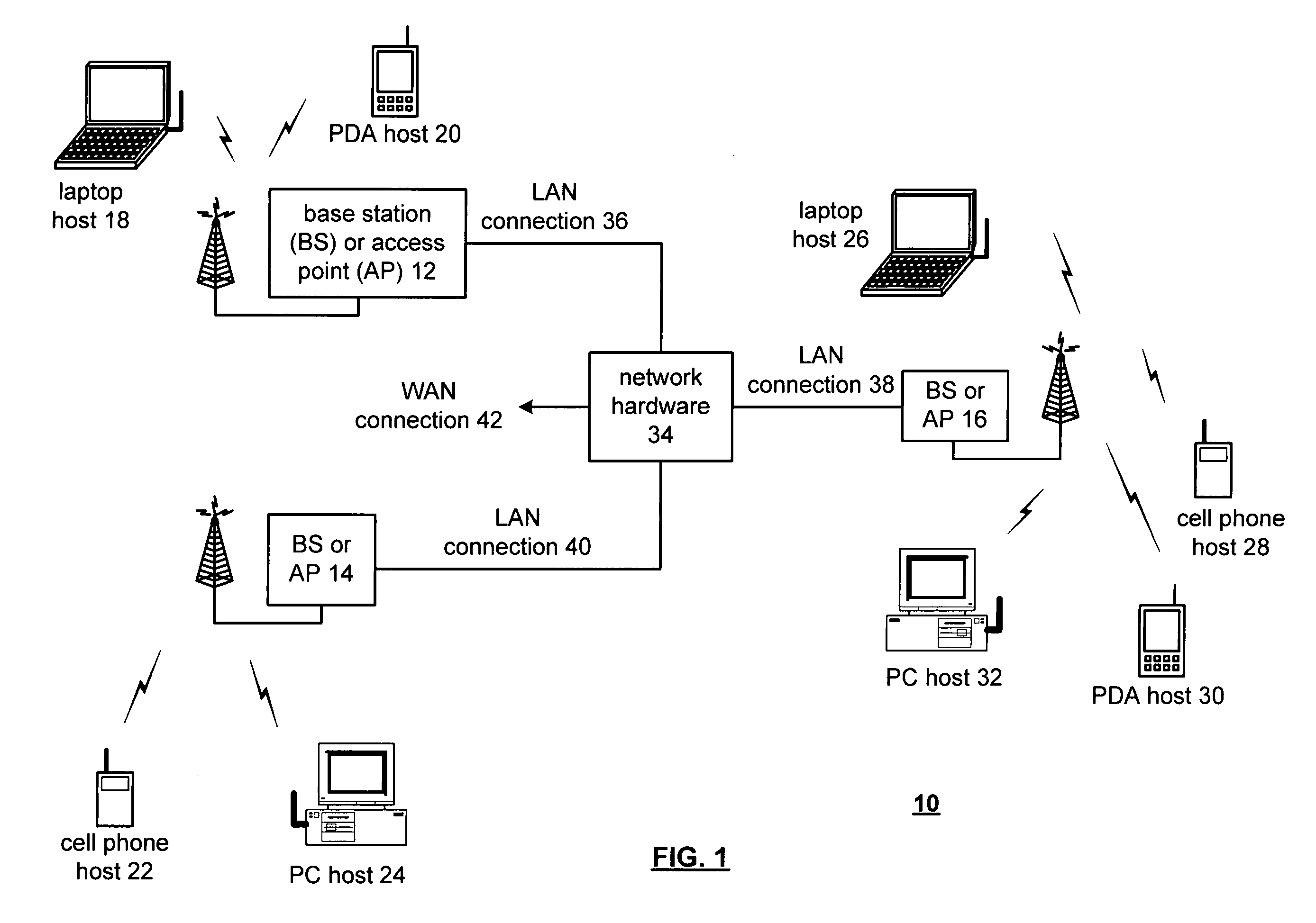
[0020]FIG. 1 is a schematic block diagram illustrating a communication system 10 that includes a plurality of base stations and / or access points 12–16, a plurality of wireless communication devices 18–32 and a network hardware component 34. The wireless communication devices 18–32 may be laptop host computers 18 and 26, personal digital assistant hosts 20 and 30, personal computer hosts 24 and 32 and / or cellular telephone hosts 22 and 28. The details of the wireless communication devices will be described in greater detail with reference to FIG. 2.

[0021]The base stations or access points 12–16 are operably coupled to the network hardware 34 via local area network connections 36, 38 and 40. The network hardware 34, which may be a router, switch, bridge, modem, system controller, et cetera provides a wide area network connection 42 for the communication system 10. Each of the base stations or access points 12–16 has an associated antenna or antenna array to communicate with the wirele...


PUM


Abstract

A method for determining a peak value of a radio frequency (RF) signal begins by receiving an RF signal. The method continues by high pass filtering the RF signal to produce a first input. The method continues by rectifying the first input signal with respect to a rectifying input to produce a rectified signal. The method continues by low pass filtering the rectified signal to produce the peak value.

Description

[0001]This patent application is claiming priority under 35 USC § 120 as a continuing patent application of patent application entitled High Frequency Signal Peak Detector, having a Ser. No. of 10 / 645,028, and a filing date of Aug. 21, 2003, and now U.S. Pat. No. 6,836,156. this appln. claims the benefit of Ser. No. 60 / 465,426 filed Apr. 25, 2003.BACKGROUND OF THE INVENTION[0002]1. Technical Field of the Invention[0003]This invention relates generally to communication systems and more particularly to transmit power control within such communication systems.[0004]2. Description of Related Art[0005]Communication systems are known to support wireless and wire lined communications between wireless and / or wire lined communication devices. Such communication systems range from national and / or international cellular telephone systems to the Internet to point-to-point in-home wireless networks. Each type of communication system is constructed, and hence operates, in accordance with one or m...

Claims


Application Information

Patent Timeline
Patent Type & Authority Patents(United States)
IPC IPC(8): G01R19/00G01R19/04H03K5/153H04B1/00H04B15/00H04B17/00
CPCG01R19/04H04B17/318
Inventor CHIEN, HUNG-MING
Owner QUALCOMM INC
Why Eureka
Try Eureka