Cross-connect method and cross-connect apparatus

a technology of cross-connecting and cross-connecting devices, applied in the field of cross-connecting methods and cross-connecting devices, can solve problems such as excessive power consumption, and achieve the effect of reducing power consumption

Inactive Publication Date: 2005-12-20
FUJITSU LTD
View PDF6 Cites 111 Cited by
  • Summary
  • Abstract
  • Description
  • Claims
  • Application Information

AI Technical Summary

Benefits of technology

[0020]In the cross-connect apparatus according to the present invention, the cross-connect control section controls the cross-connect operation of the cross-connect section so as to select the sign

Problems solved by technology

A redundant configuration enables a cross-connect operation on a signal which is not output from the PSW 10-1d, t

Method used


Image

  • Cross-connect method and cross-connect apparatus
  • Cross-connect method and cross-connect apparatus
  • Cross-connect method and cross-connect apparatus

Examples


Embodiment Construction

(a) Aspects of the Present Invention

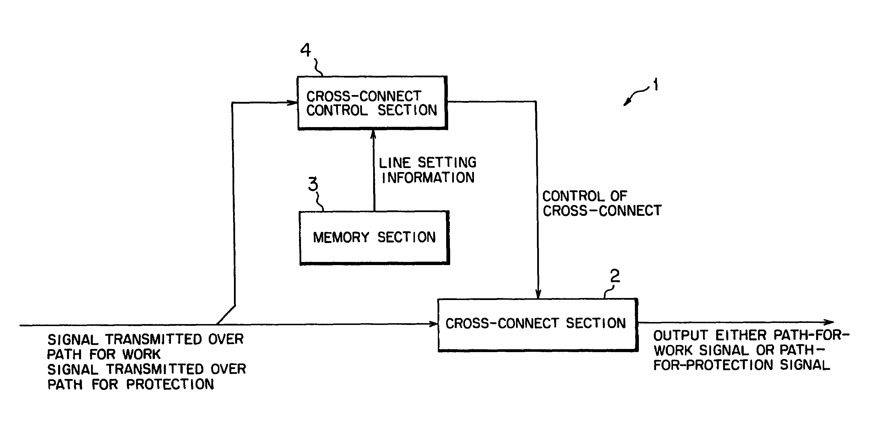
[0034]A cross-connect method according to the present invention comprises a step of retaining line setting information required for a cross-connect operation and a step of controlling the cross-connect operation of a main signal based on the line setting information in such a manner that one of a path-for-work signal transmitted over a path-for-work and a path-for-protection signal transmitted over a path-for-protection is to be selectively output.

[0035]Under the cross-connect method according to the present invention, the cross-connect control is performed in the step of controlling in a way so as to select a signal of better quality from the signal transmitted over the path for work and the signal transmitted over the path for protection based on the line setting information. The function of the hard switch that has conventionally been used for a purpose other than a cross-connect operation can be applied to cross-connect operation, thereby prev...


PUM


Abstract

There is described a cross-connect apparatus which can apply a cross-connect operation in place of a function of a hard switch that has conventionally been used for a purpose other than a cross-connect operation, by selection of line setting information used for path switching and service selection operations, and by performing a cross-connect operation based on the information, thereby preventing redundant configuration of the cross-connect apparatus and diminishing power consumption.

Description

BACKGROUND OF THE INVENTION[0001](1) Field of the Invention[0002]The present invention relates to a cross-connect method and a cross-connect apparatus suitable for use with a synchronous digital hierarchy (SDH) transmission system.[0003](2) Description of the Related Art[0004]A ring network (hereinafter sometimes simply referred to as a “ring”) generally comprises a plurality of node devices (SDH transmission devices) connected together by means of high-speed transmission paths (for work and for protection).[0005]Each of the node devices constituting the ring network [for example, an add-and-drop multiplexer (ADM)] is arranged so as to be able to receive a signal sent from another low-speed network of a lower hierarchical level by way of a low-speed transmission path and to add the signal to a high-speed transmission path (transmission path for work) so as to transmit the signal to another node device connected to the ring; to permit a signal—which is transmitted from another node d...

Claims


Application Information

Patent Timeline
IPC IPC(8): H04M3/22G01R31/08H04B1/74H04J3/00H04J3/08H04L12/70H04Q11/04
CPCH04L49/101H04L49/552H04Q11/04H04L49/25H04L49/254H04L49/557H04Q2213/13076H04Q2213/13167H04Q2213/13292H04Q2213/13393
Inventor KAWAGUCHI, MITSUHIROTANI, SHIGEO
Owner FUJITSU LTD
Why Eureka
Try Eureka