Site-to-site dynamic virtual local area network

a virtual local area network and site-to-site technology, applied in data switching networks, frequency-division multiplexes, instruments, etc., can solve the problems of not being accessible to non-customer suts on conflicting custom configurations with the main manufacturing network, and causing operator errors, so as to reduce the amount of operator intervention needed, and facilitate configuration

Inactive Publication Date: 2005-12-20
DELL PROD LP
View PDF15 Cites 8 Cited by
  • Summary
  • Abstract
  • Description
  • Claims
  • Application Information

AI Technical Summary

Benefits of technology

[0011]A principal advantage of this embodiment is that it provides a method for dynamically, rather than statically, connecting an SUT to a private VLAN in a computer manufacturing environment, thereby reducing the amount of operator intervention needed to perform custom configuration of SUTs.
[0012]Another advantage of this embodiment is that the connection of the SUT to a private VLAN can be automated, further reducing the amount of ope...

Problems solved by technology

Often, this sort of custom configuration would conflict with the main manufacturing network.
Alternatively, it may require the transmission of data that is proprietary to the customer and hence, should not be made accessible to non-customer SUTs on the main manufacturing network.
Clearly, the problem with this...

Method used


Image

  • Site-to-site dynamic virtual local area network
  • Site-to-site dynamic virtual local area network
  • Site-to-site dynamic virtual local area network

Examples


second embodiment

[0052]FIG. 10 is a system block diagram illustrating an implementation of a site-to-site DVLAN arrangement 1000 according to a As will be evident, the arrangement 1000, unlike the arrangement 900, is scalable. In FIG. 10, a local site 1002 includes a plurality of SUTs 1004 on multiple VPNs are connected to a core CAT 1006 via an Ethernet link 1008 including a CAT 1010, such that the Ethernet link 1008 is capable of promoting all of the various VPNs to which the SUTs 1004 are connected. A similar arrangement exists at a remote site 1012, a plurality of SUTs 1014 on multiple VPNs are connected to a core CAT 1016 via an Ethernet trunk 1018 including a CAT 1020. Although not shown in FIG. 10, it will be recognized that the SUTs 1004, 1014, will typically reside in burn racks. Again, the Ethernet link 1018 is capable of promoting all of the various VPNs to which the SUTs 1014 are connected.

[0053]The core CATs 1006, 1016, are connected to one another via an ATM connection 1030 that inclu...

third embodiment

[0054]FIG. 11 is a system block diagram illustrating an implementation of a site-to-site DVLAN arrangement 1100 according to a As will be evident, the arrangement 1100, like the arrangement 1000, is scalable. In FIG. 11, a local site 1102 includes a plurality of SUTs 1104 on multiple VPNs are connected to a core CAT 1106 via an Ethernet link 1108 including a CAT 1110, such that the Ethernet link 1108 is capable of promoting all of the various VPNs to which the SUTs 1104 are connected. Although not shown in FIG. 11, it will be recognized that the SUTs 1104 will typically reside in burn racks. At a remote site 1112, a plurality of customer sites 1114 are connected to a core CAT 1116 via an Internet connection 1117, which is made up of VPN “tunnels” established over the Internet to customer sites 1114, and an Ethernet link 1118 including a shared router 1120 such that the Ethernet link 1118 is capable promoting all of the various VPNs to which the SUTs 1104 are connected. The customer...

fourth embodiment

[0057]FIG. 12 is a system block diagram illustrating an implementation of a site-to-site DVLAN arrangement 1200 according to a As will be evident, the arrangement 1200, like the arrangements 1000 and 1100, is scalable. In FIG. 12, a local site 1202 includes a plurality of SUTs 1204 on multiple VPNs are connected to a core CAT 1206 via an Ethernet link 1208 including a CAT 1210, such that the Ethernet link 1208 is capable of promoting all of the various VPNs to which the SUTs 1204 are connected. Although not shown in FIG. 12, it will be recognized that the SUTs 1204 will typically reside in burn racks. At a remote site 1212, a single customer site 1214 is connected to a core CAT 1216 via a private high-speed connection 1215, such as a frame-relay or ISDN connection, including a router 1216, for providing a point-to-point connection between the customer site 1214 and the remote site 1212.

[0058]The core CATs 1206, 1216, are connected to one another via an ATM connection 1230 that incl...


PUM


Abstract

A system for dynamically implementing a plurality of virtual local area networks (“VLANs”) across multiple sites is provided. The system includes a first VLAN-capable switch at a first site; a first system under test (“SUT”) connected to the first VLAN-capable switch via a first burn rack switch; a second VLAN-capable switch located at a second site remote from the first site; a second SUT connected to the second VLAN-capable switch via a second burn rack switch. The first and second VLAN-capable switches are connected such that the first and second SUTs are connected to a single virtual private network (“VPN”). The connection may include either first and second routers respectively connected to the first and second VLAN-capable switches and interconnected via a T1 line or an ATM connection. The system may also include a first VLAN-capable switch located at a first site; a first system under test (“SUT”) connected to the first VLAN-capable switch via a first burn rack switch; a second VLAN-capable switch located at a second site remote from the first site; a customer network located at a customer site remote from the first and second sites and connected to the second VLAN-capable switch via a router; and an ATM connection between the first and second VLAN-capable switches such that the first SUT and the customer network are connected to a single virtual private network (“VPN”). In this embodiment, the connection between the second site and customer site may be either an Internet connection or a high speed point-to-point connection.

Description

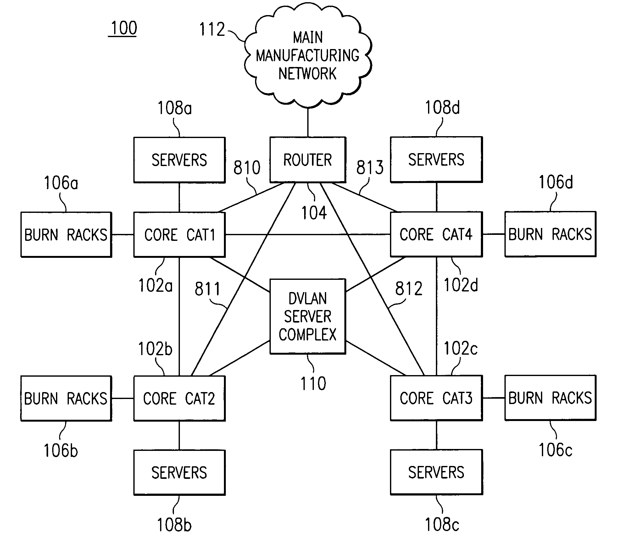
CROSS-REFERENCE TO RELATED APPLICATIONS[0001]This application claims priority to and is a divisional of co-owned U.S. patent application Ser. No. 09 / 426,232, filed Oct. 22, 1999 now U.S. Pat. No. 6,654,347, by Wiedeman et al., entitled SITE-TO-SITE DYNAMIC VIRTUAL LOCAL AREA NETWORK, which is incorporated herein by reference in its entirety.[0002]This application relates to co-owned co-pending U.S. patent application filed concurrently herewith by Wiedeman et al., and entitled SITE-TO-SITE DYNAMIC VIRTUAL LOCAL AREA NETWORK, which is incorporated herein by reference.[0003]This application relates to U.S. Pat. No. 6,285,967, issued on Sep. 4, 2001, entitled TROUBLESHOOTING COMPUTER SYSTEMS DURING MANUFACTURING USING STATE AND ATTRIBUTE INFORMATION, naming Subhashini Rajan, Roger Wong and Richard D. Amberg as inventors; U.S. Pat. No. 6,477,486, issued on Nov. 5, 2002, entitled AUTOMATIC LOCATION DETERMINATION OF DEVICES UNDER TEST, naming Subhashini Rajan and Roger Wong as inventors; ...

Claims


Application Information

Patent Timeline
IPC IPC(8): H04L12/46
CPCH04L12/4675
Inventor WIEDEMAN, DENNIS M.BAKER, EUGENEPOTTER, DWAYNE R.AMBERG, RICHARD
Owner DELL PROD LP
Why Eureka
Try Eureka