
Variable redundancy cyclic code encoders

a code encoder and variable redundancy technology, applied in the field of error correction systems, can solve problems such as errors, extra time associated with encoding and decoding data, and complexity of encoding and decoding systems

Inactive Publication Date: 2005-12-20
MAXTOR
View PDF12 Cites 24 Cited by
  • Summary
  • Abstract
  • Description
  • Claims
  • Application Information

AI Technical Summary

Benefits of technology

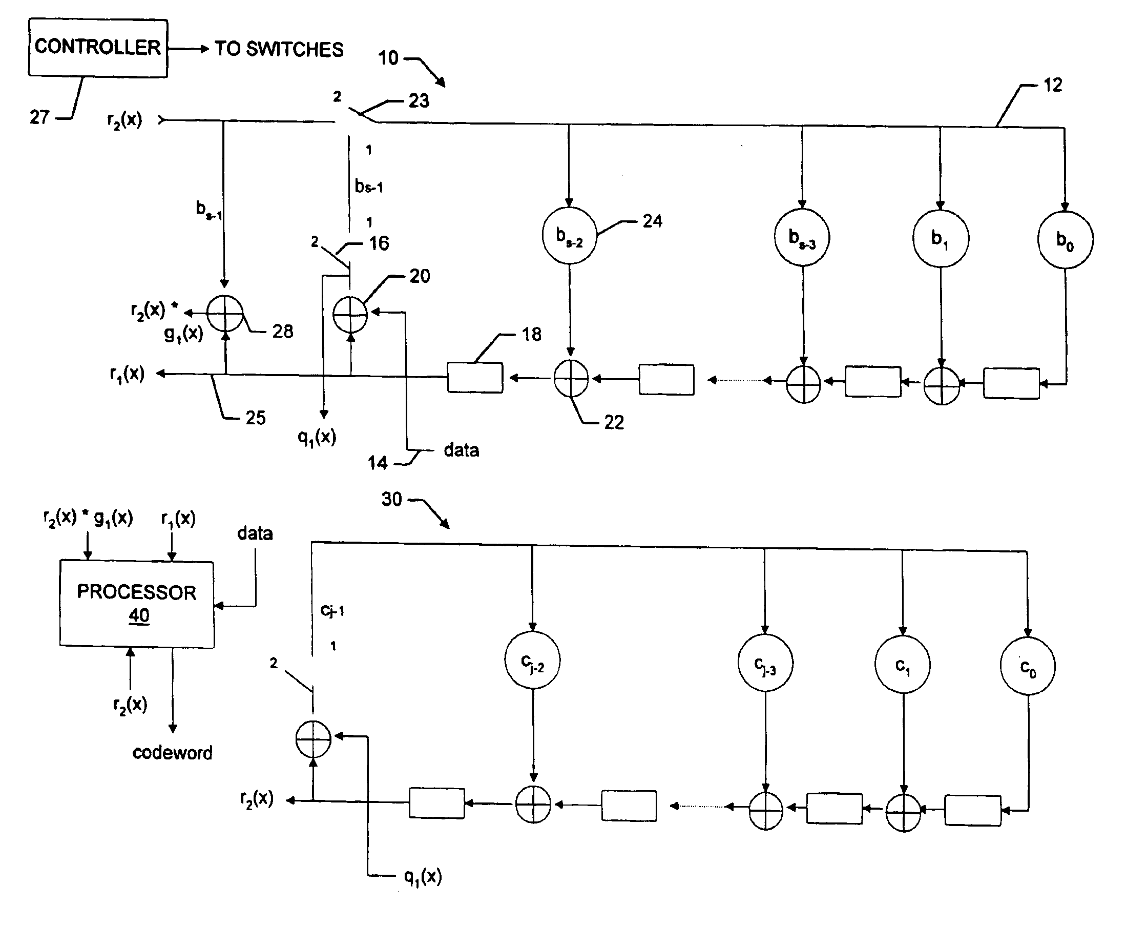
"The patent describes a system that encodes data using a cyclic code generator polynomial to produce data code words with a corresponding number of ECC symbols. The system has multiple stages that allow for more flexibility in selecting the number of ECC symbols. The system also uses the same circuitry to decode the code and perform error correction operations. The technical effect of the patent is to provide a more efficient and flexible way to encode and decode data using ECC symbols."

Problems solved by technology

The errors may occur, for example, because of inter-symbol interference, a defect in the disk, or noise.
Some of the trade-offs for including increased error correction information on the disk are the extra time associated with encoding and decoding the data and the complexity of the encoding and decoding systems.
However, as discussed in the article, the encoding is associated with a latency that is attributable to the delay through the chain of j feedback adders.
Known prior systems use complex and / or time consuming encoding / decoding systems to produce the code words with different numbers of ECC symbols.
However, when the data and the retained ECC symbols are later decoded, the system must use a relatively complex and time consuming error-and-erasure decoding scheme to perform error-only decoding.
Such a system works well for ECCs that include relatively small numbers of ECC symbols, however, the delay associated with the feedback adder chain effectively prohibits the use of the circuit for codes with relatively large numbers of ECC symbols.

Method used


Image

  • Variable redundancy cyclic code encoders
  • Variable redundancy cyclic code encoders
  • Variable redundancy cyclic code encoders

Examples


Embodiment Construction

[0021]The discussion below is separated into sections, a first section discusses the mathematical theory, a second discusses one embodiment of the encoder and a third section discusses another embodiment of the encoder. All mathematical operations are is Galois Field operations.

[0022]A. The Theory

[0023]The k data symbols to be encoded may be represented as the coefficients of a degree k−1 polynomial d(x). The ECC is a cyclic code with a generator polynomial g(x) of degree n−k, and the data is encoded by dividing it by the generator polynomial. The result is a quotient q(x) of degree n−(n−k)−1=k−1 and a remainder r(x) of at most degree n−k−1. The coefficients of the remainder r(x) are included in the code word as the n−k ECC symbols. The code word data is thus:

d(x)*xn−k=q(x)*g(x)+r(x)  eqn. 1

where xn−k represents a shifting of the data to the appropriate position in the code word.

[0024]For a generator polynomial with two factors:

g(x)=g1(x)*g2(x)

where g1(x) has degree s and g2(x) has ...


PUM


Abstract

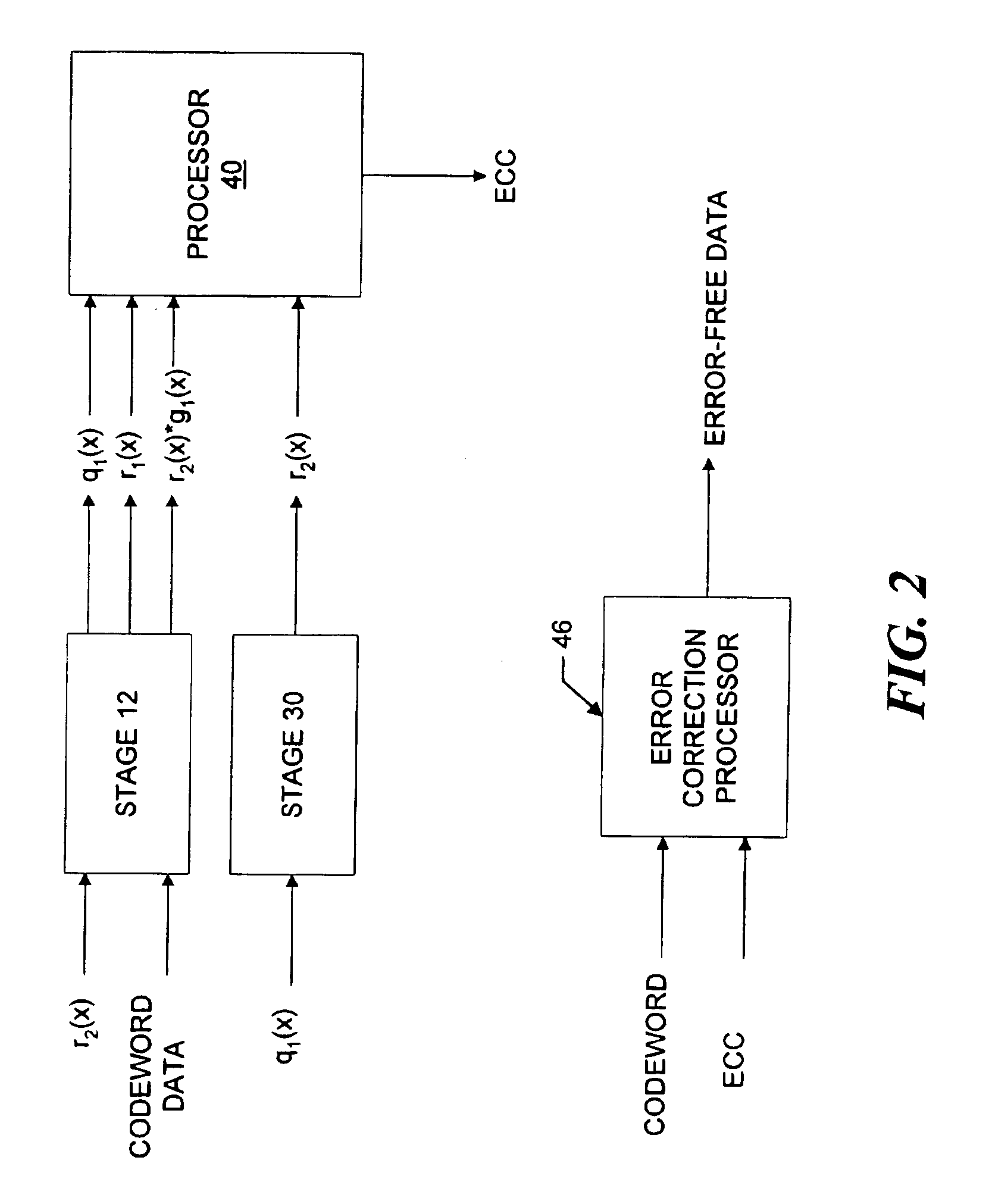
A multiple-stage encoder encodes the data in accordance with one, two, . . . , or f factors of an associated cyclic code generator polynomial g(x)=g1(x)*g2(x)* . . . *gf(x) to produce data code words that include a selected number of ECC symbols. The encoder encodes the data d(x) in a first stage using a first factor gm(x) of a selected polynomial ps(x) to produce d(x)*xs=q1(x)g1(x)+r1(x), where q1(x) is a quotient and r1(x) is a remainder and g1(x) has degree s. In a next stage the encoder encodes q1(x) using a next factor gm(x) of the selected polynomial to produce qm(x)=q1(x)gm(x)+rm(x) and so forth, until the remainders associated with all of the factors of the selected generator polynomial have been produced. The system then manipulates the remainders to produce a remainder rs(x) that is associated with the selected polynomial ps(x), and uses a cyclically shifted version of the remainder rs(x) as the code word ECC symbols. The same circuitry is used to both produce and manipulate the remainders, and may also be used for decoding the code words in accordance with the selected polynomials.

Description

BACKGROUND OF THE INVENTION[0001]1. Field of the Invention[0002]The invention relates generally to error correction systems and, more particularly, to systems that use selected numbers of redundancy symbols.[0003]2. Background Information[0004]Data stored on magnetic media, such as magnetic disks, are typically stored in encoded form, so that errors in the stored data can possibly be corrected. The errors may occur, for example, because of inter-symbol interference, a defect in the disk, or noise. If more errors are likely, and the system is thus required to correct greater numbers of errors, more error correction information in the form of redundancy symbols is required to be stored on the disk. Some of the trade-offs for including increased error correction information on the disk are the extra time associated with encoding and decoding the data and the complexity of the encoding and decoding systems.[0005]Encoders for encoding data in accordance with cyclic error correction codes...

Claims


Application Information

Patent Timeline
Patent Type & Authority Patents(United States)
IPC IPC(8): H03M13/00H03M13/15
CPCH03M13/15
Inventor WENG, LIH-JYH
Owner MAXTOR
Learn More