Reversible heat engine

a heat engine and reverse technology, applied in the field of heat engines, can solve the problems of idleness of solar water heaters, and achieve the effect of higher thermal efficiency

Inactive Publication Date: 2005-12-27
CARNAHAN ERIC SCOTT
View PDF4 Cites 32 Cited by
  • Summary
  • Abstract
  • Description
  • Claims
  • Application Information

AI Technical Summary

Benefits of technology

[0037]Accordingly, a feature and advantage of the present invention is its ability to function as either a forward heat engine producing a work output or a reverse heat engine (e.g., an air conditioner, refrigerator, or heat pump) at any given selected moment.
[0038]Another feature and advantage of the present invention is its ability to yield significantly higher thermal efficiencies than existing heat engines operating within the same temperature ranges.

Problems solved by technology

Solar water heaters sit idle most of the day because most hot water use occurs in the morning or at night.

Method used


Image

  • Reversible heat engine
  • Reversible heat engine
  • Reversible heat engine

Examples


Embodiment Construction

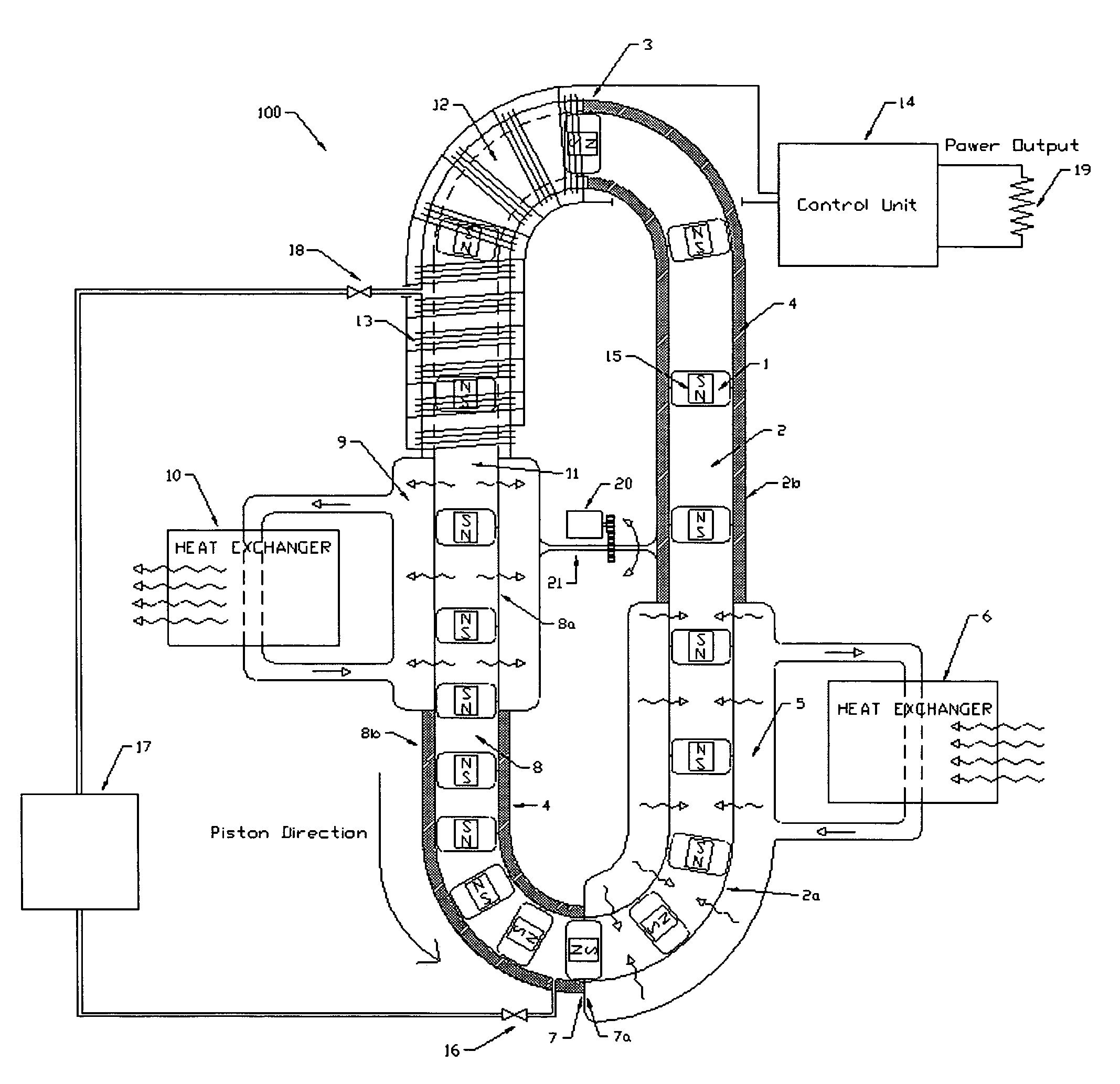
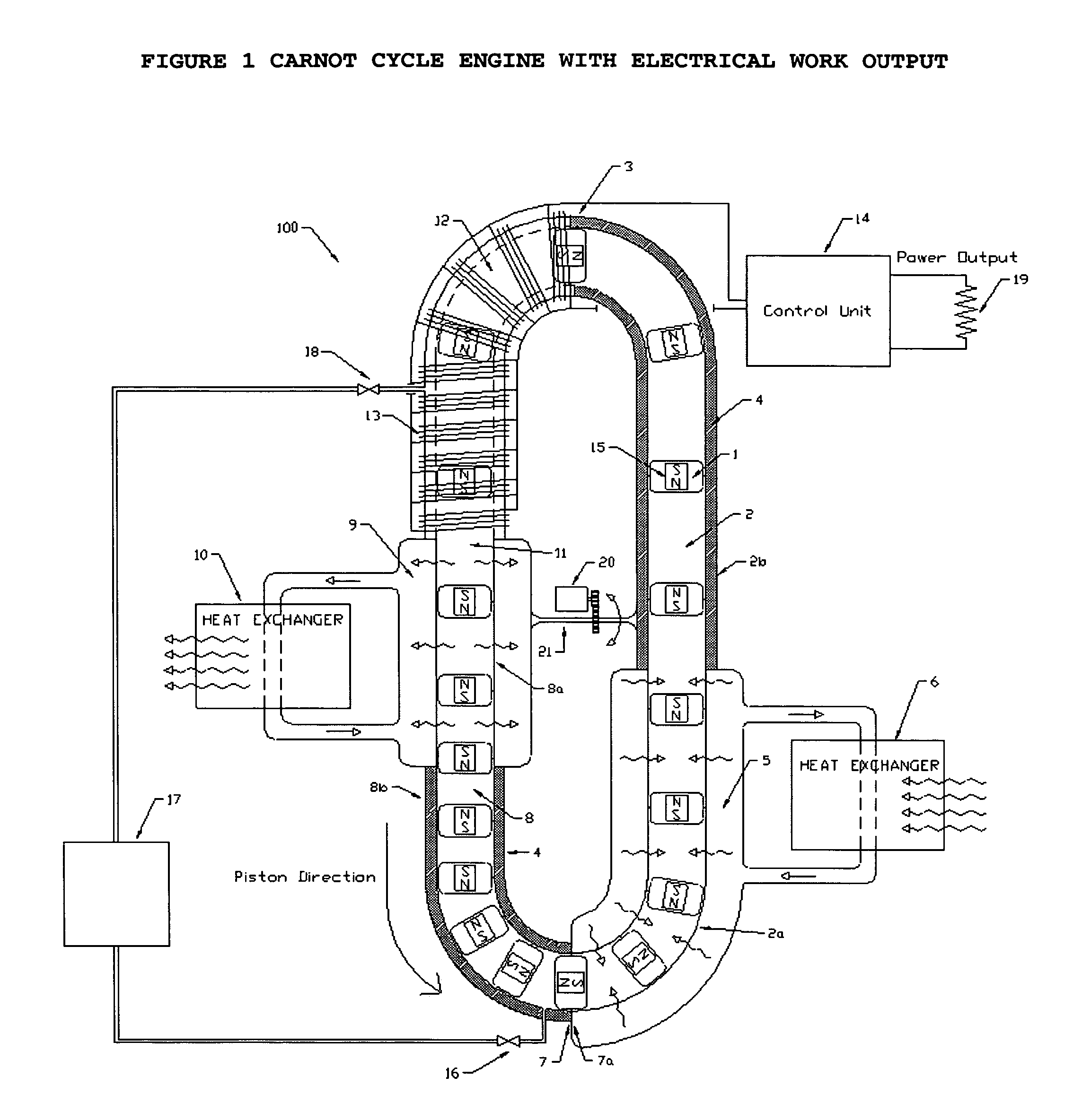
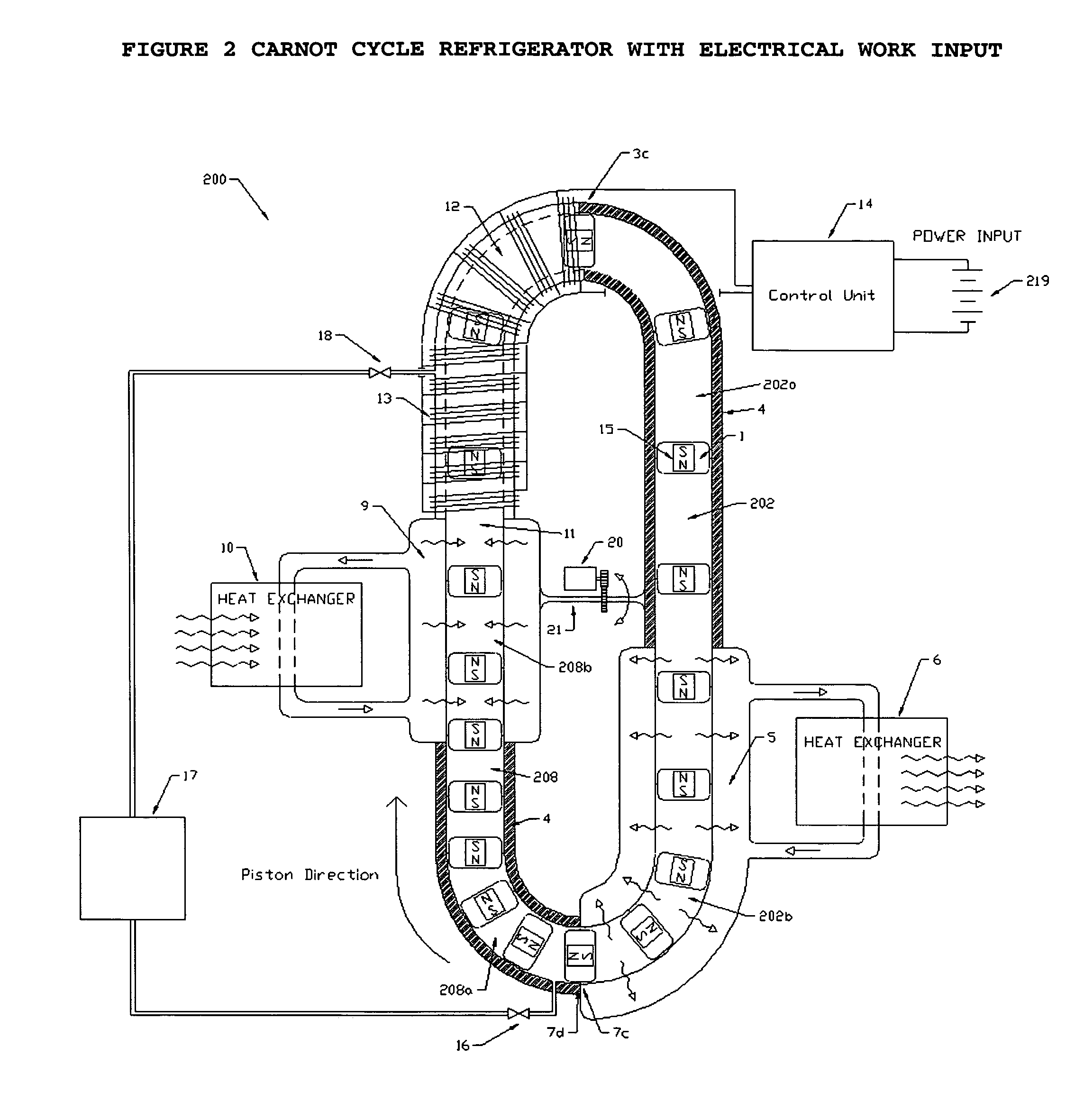
[0046]In describing the preferred and alternate embodiments of the present invention, as illustrated in FIGS. 1–5, specific terminology is employed for the sake of clarity. The invention, however, is not intended to be limited to the specific terminology so selected, and it is to be understood that each specific element includes all technical equivalents that operate in a similar manner to accomplish similar functions.

[0047]Referring now to FIG. 1, illustrated therein is heat engine 100, wherein the engine pistons 1 enter the compression cylinder 8 at the entry point 11 of the cylinder 8. A working fluid such as air occupies the space between the pistons 1 within the cylinder 8. Gravity pulls the pistons 1 and the working fluid between pistons 1 downward through the cylinder 8 compressing the working fluid.

[0048]A heat transfer fluid 9 is circulated around the outside wall of the top section of the compression cylinder 8a. Heat generated by the compression process is absorbed by the...


PUM


Abstract

A heat engine capable of significantly higher thermal efficiencies than existing heat engines operating within the same temperature ranges, wherein the heat engine can operate efficiently as either a forward heat engine or as a reverse heat engine at any given selected moment; thus, permitting the present heat engine to be utilized as an air conditioner or heat pump, or, alternatively, if a heat source is provided to the engine, as a forward heat engine producing a work output.

Description

TECHNICAL FIELD[0001]The present invention relates generally to heat engines, and more specifically to a reversible heat engine of the piston-cylinder type. The present invention can be operated as either a forward heat engine, producing a power output if a high temperature heat source is provided, or, alternatively, as a reverse heat engine (e.g. a refrigerator or heat pump) if a power input is provided.BACKGROUND OF THE INVENTION[0002]A forward heat engine is a device that converts thermal energy (heat) into mechanical work. A reverse heat engine is a device that utilizes a mechanical work input to transfer heat from a body at a low temperature to a body at a higher temperature. Countless varieties of both forward and reverse heat engines have been created. Examples of common forward heat engines include the internal combustion engine, gas turbine engines, steam turbine engines and Stirling engines. Examples of reverse heat engines include common air conditioners, refrigerators an...

Claims


Application Information

Patent Timeline
Patent Type & Authority Patents(United States)
IPC IPC(8): F02G1/043F02G1/044F25B9/00
CPCF02G1/0435F02G1/044F25B9/00F25B2400/073
Inventor CARNAHAN, ERIC SCOTT
Owner CARNAHAN ERIC SCOTT
Why Eureka
Try Eureka