Light guide plate

a technology of light guide plate and guide plate, which is applied in the direction of lighting and heating apparatus, instruments, machines/engines, etc., can solve the problems of difficult to reduce the thickness of direct type backlight module, and uneven brightness distribution of liquid crystal panel. to achieve the effect of improving the uniformity of luminance of backlight modul

Inactive Publication Date: 2005-12-27
HON HAI PRECISION IND CO LTD
View PDF16 Cites 66 Cited by
  • Summary
  • Abstract
  • Description
  • Claims
  • Application Information

AI Technical Summary

Benefits of technology

[0010]In view of the above-described drawbacks, an object of the present invention is to provide a light guide plate used in a backlight module for a liquid crystal display which can improve the uniformity of luminance of the backlight module.

Problems solved by technology

Generally, in a direct type backlight module, a light source is disposed inside the display area of the liquid crystal panel, thus, the brightness distribution of the liquid crystal panel is not uniform and the liquid crystal and the TFT switching elements can be damaged by the heat energy of the light source.
Furthermore, it is very difficult to reduce the thickness of the direct type backlight module.
Thus, it is difficult to achieve an uniformity in light output from the emitting face since the ratio of the area of the dots as a function of total area increases linearly from the light source to the region near the end edge of reflection layer 4.

Method used


Image

  • Light guide plate
  • Light guide plate
  • Light guide plate

Examples


Embodiment Construction

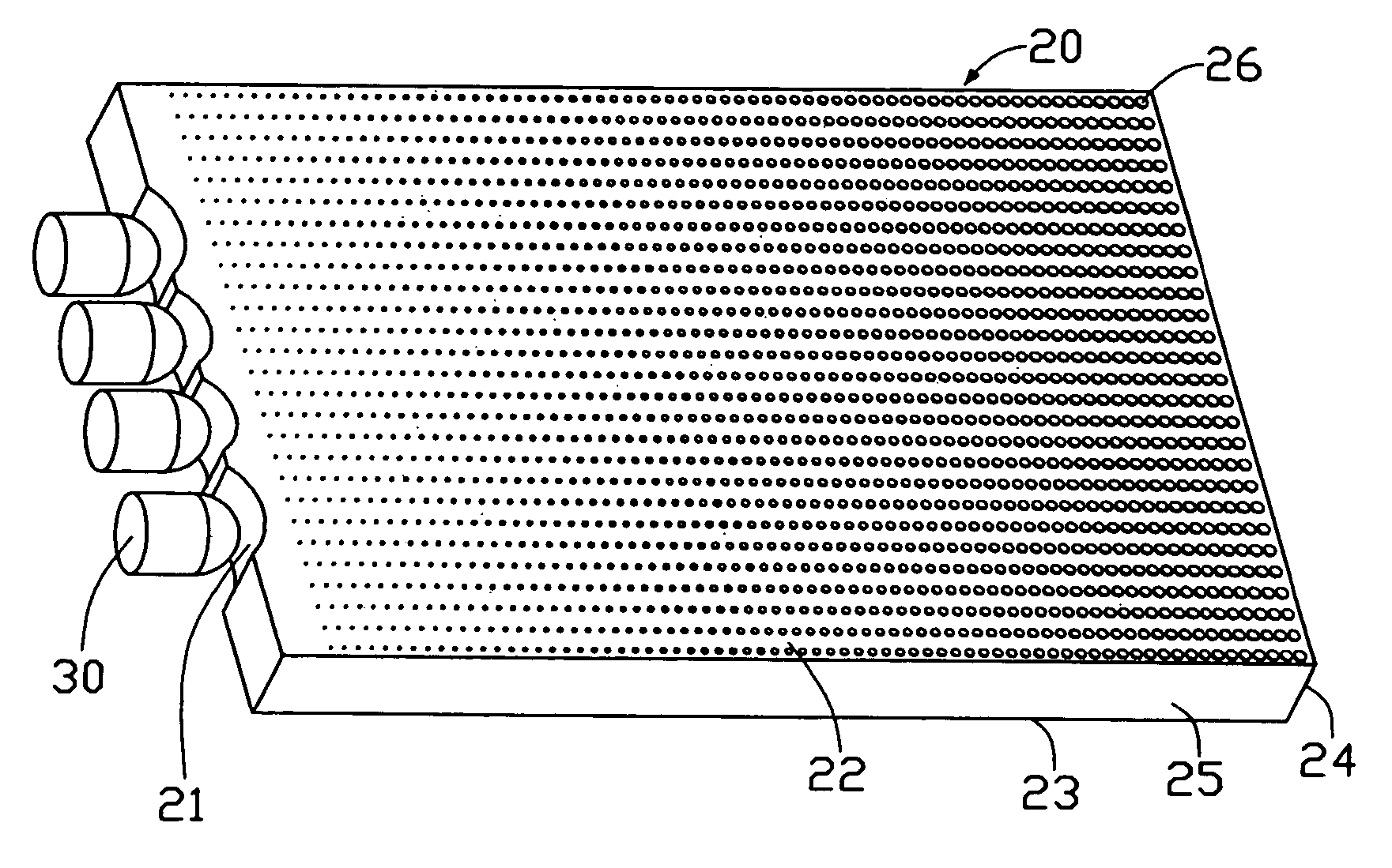
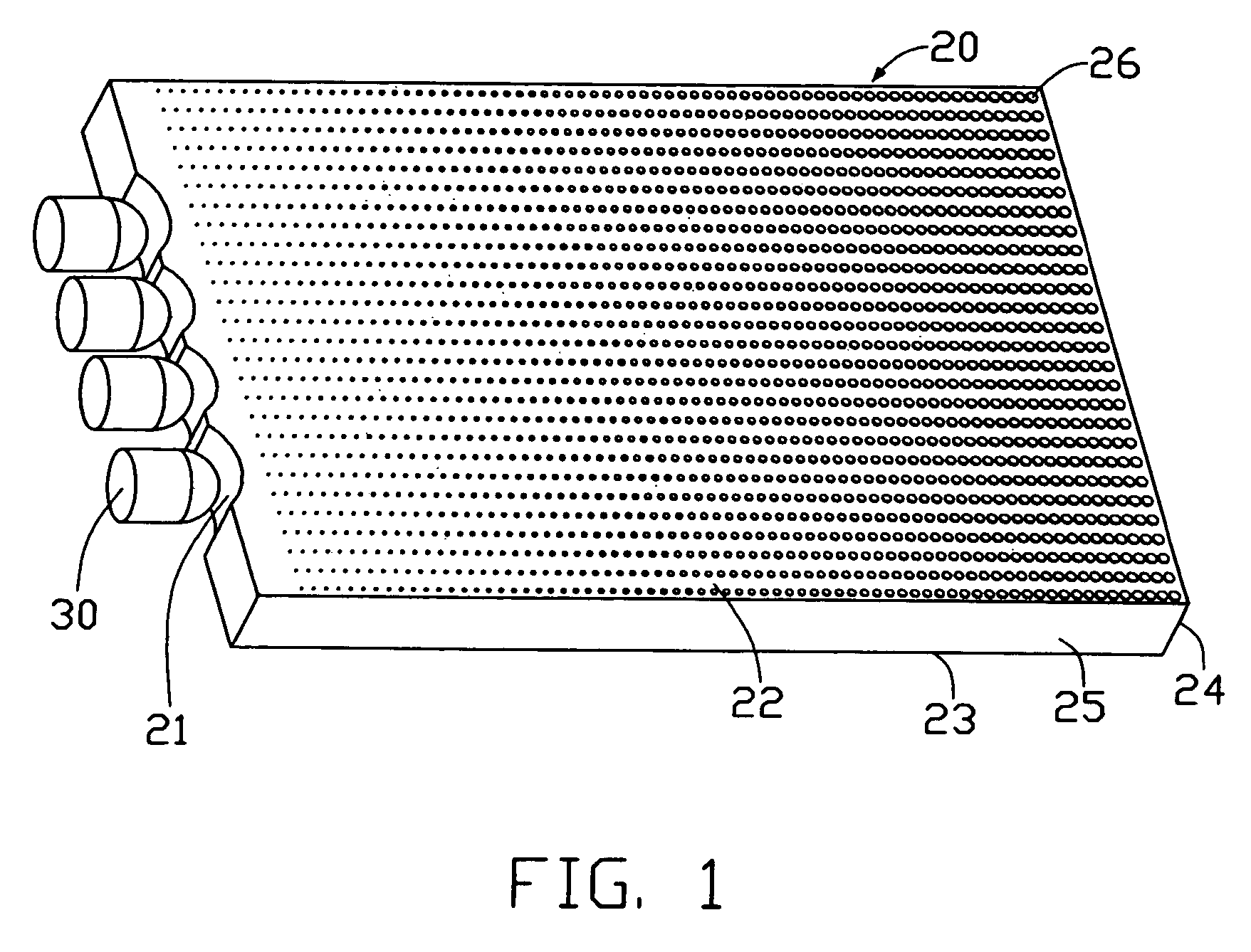
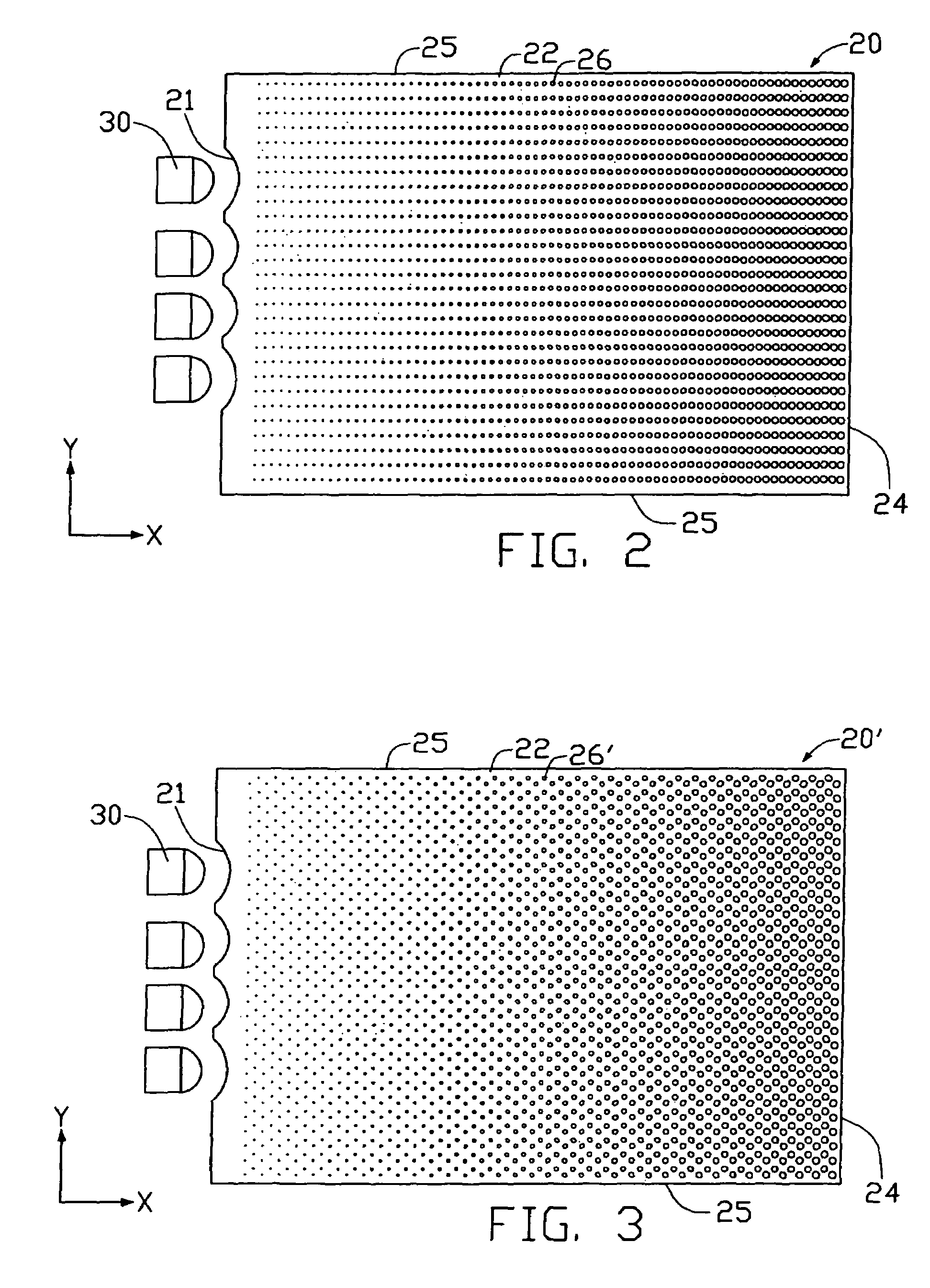
[0018]Referring to FIG. 1, a light guide plate 20 in accordance with a preferred embodiment of the present invention is substantially a rectangular plate, and is used in a backlight module. The light guide plate 20 comprises a light input end 21, a light output face 23 adjacent the light input end 21, an end face 24 opposite to the light input end 21, a back face 22 opposite to the light output face 23 and adjacent the light input end 21, and two opposite side faces 25 (only one labeled).

[0019]The light guide plate 20 is made from a transparent material such as acrylic ester, polycarbonate, polyvinyl ester, or glass. The light input end 21 comprises a plurality of evenly spaced, arcuate concave surfaces. A plurality of light sources 30 are provided adjacent the light input end 21, respectively corresponding in number and position to the concave surfaces of the light input end 21. The light sources 30 can be diodes or other suitable point light sources. Incident light generated from ...


PUM


Abstract

A light guide plate (20) includes a light input end (21), a light output face (23) adjacent the light input end, and a back face (22) opposite to the light output face. A plurality of fine dots (26) are formed on the back face arranged in a uniform, rectangular array. The dots in a same column have a same size. The dots in a same row increase in size. A radius r of the dots in each row thereof varies as a function of a column number X of a given dot, in accordance with the formula: r=A+BX+CX2+DX3+EX4+FX5, wherein: the column number X varies in consecutive whole numbers from a value of one for the column nearest the light input end to a maximum value for the column most distal from the light input end; and A, B, C, D, E, and F are constants.

Description

BACKGROUND OF THE INVENTION[0001]1. Field of the Invention[0002]The present invention relates to a light guide plate used in a backlight module for a liquid crystal display, and more particularly to a light guide plate having a dot pattern used in a backlight module for a liquid crystal display.[0003]2. Description of Prior Art[0004]Generally, a liquid crystal display device includes a liquid crystal panel having two substrates and a liquid crystal inserted therebetween, and a backlight module disposed under the liquid crystal panel. The backlight module is arranged to distribute light from a light source uniformly over the surface of the liquid crystal panel. There are several kinds of backlight modules, including a direct back light type (or direct type) and an edge light type. Generally, in a direct type backlight module, a light source is disposed inside the display area of the liquid crystal panel, thus, the brightness distribution of the liquid crystal panel is not uniform and...

Claims


Application Information

Patent Timeline
Patent Type & Authority Patents(United States)
IPC IPC(8): F21V8/00
CPCG02B6/0061G02B6/0036
Inventor YU, TAI-CHENGLEU, CHARLESCHEN, GA-LANE
Owner HON HAI PRECISION IND CO LTD
Why Eureka
Try Eureka