Biased utility receptacle assembly

a technology for utility receptacles and assembly parts, applied in the direction of furniture parts, table tops, coupling device connections, etc., can solve the problems of inconvenience for users, damage and/or disengagement of plugs or other connectors, and the cover member used to conceal the receptacle cannot be reliably held in the open position

Active Publication Date: 2005-12-27
KRUEGER INT
View PDF54 Cites 71 Cited by
  • Summary
  • Abstract
  • Description
  • Claims
  • Application Information

AI Technical Summary

Benefits of technology

[0006]According to a primary aspect of the present invention, a utility receptacle assembly includes a biasing member which operates to bias a cover member pivotally connected to the assembly to an open position in order to expose utility receptacles located directly beneath the cover member within the...

Problems solved by technology

Unfortunately, on many occasions the cover member used to conceal the receptacle cannot be reliably held in the open position when the receptacle is in use.
Thus, the cover member and/or receptacle may inadvertently move to a closed position when the...

Method used


Image

  • Biased utility receptacle assembly
  • Biased utility receptacle assembly
  • Biased utility receptacle assembly

Examples


Embodiment Construction

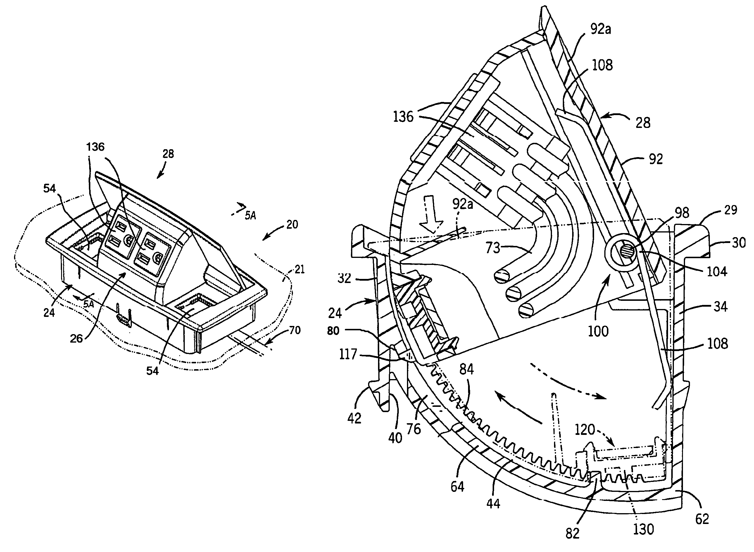
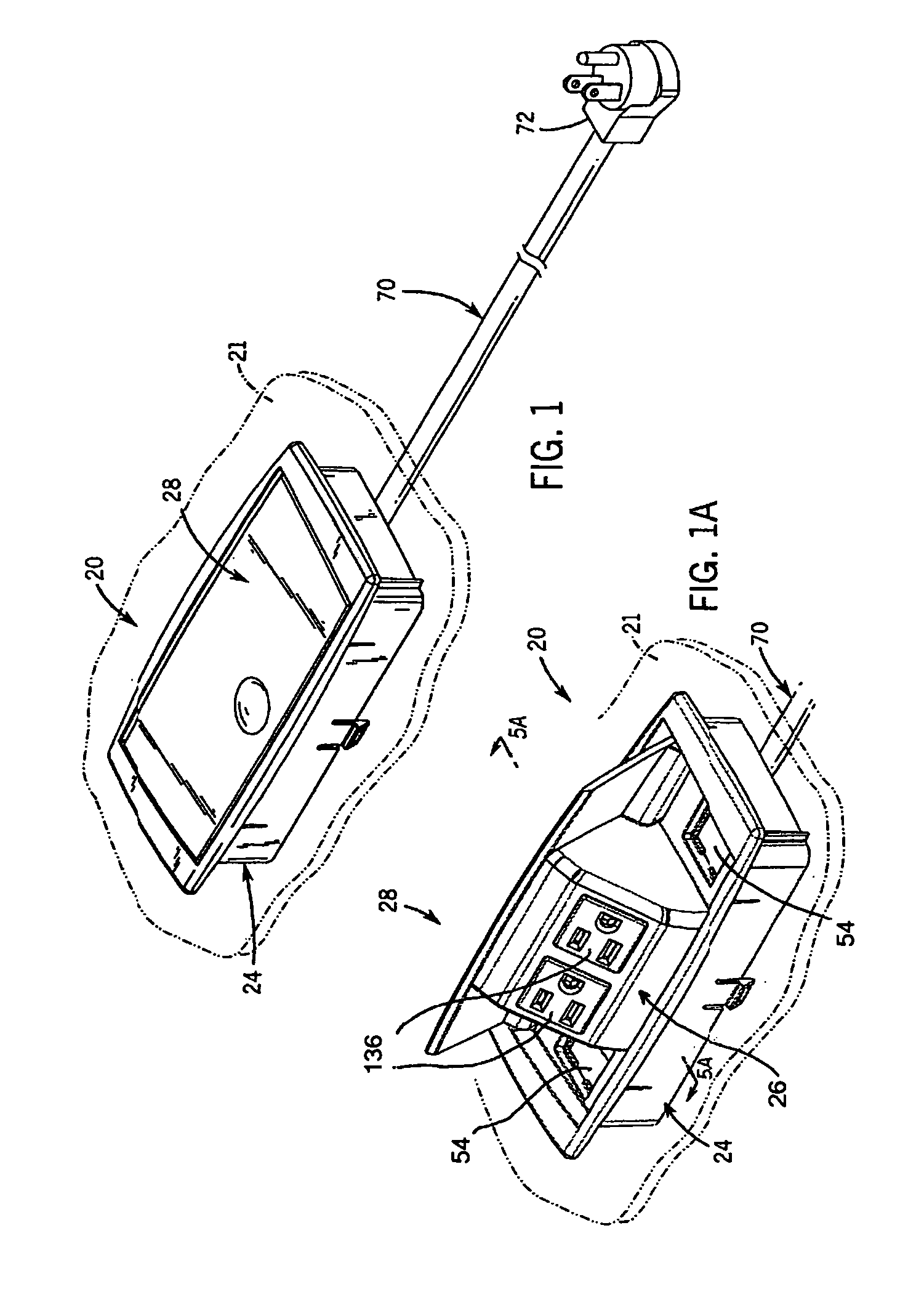
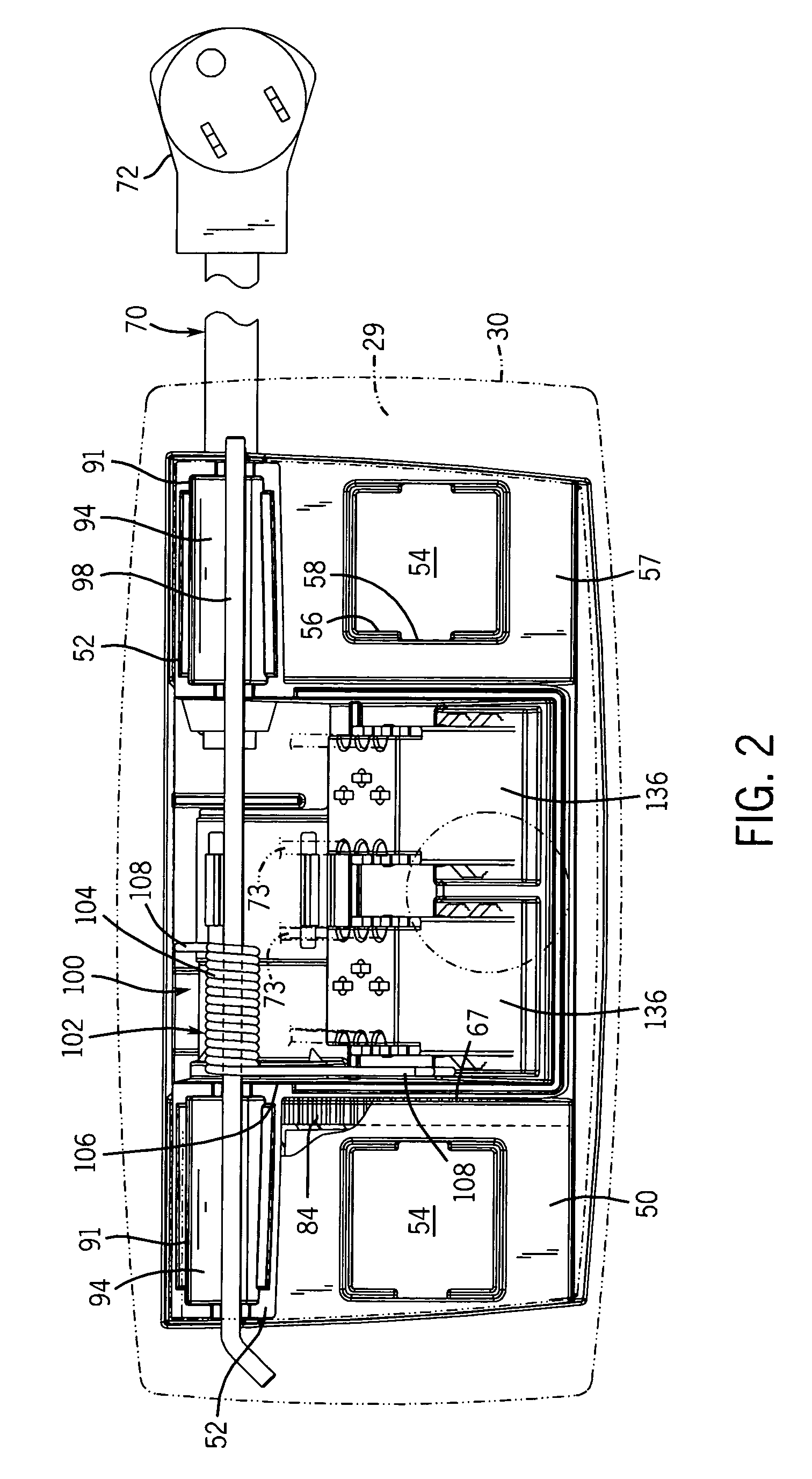
[0062]With reference now to the drawing figures in which like reference numerals designate like parts throughout the disclosure, a utility receptacle assembly in accordance with the present invention is illustrated generally at 20 in FIGS. 1 and 1A. The assembly 20 is adapted for mounting within an opening formed in a support surface 21, which may be a desk top, tabletop or any other work surface or member where it is desired to provide selective access to power and / or communication receptacles. Generally, the utility receptacle assembly 20 includes a base member 24, a utility receptacle member 26 movably mounted to the base member 24, and a cover member 28 mounted to the utility receptacle member 26 in a manner to be explained.

[0063]The utility receptacle assembly 20 is movable between a closed or inoperative position as shown in FIG. 1, in which the receptacle member 26 is completely hidden within the base member 24, and an open or operative position as shown in FIG. 1a, in whic...


PUM


Abstract

A pivoting utility receptacle assembly for use with a work surface, such as a desktop. The assembly includes a base member positionable within an opening in the work surface and a receptacle member that is pivotally mounted to the base member. A biasing member is engaged between the receptacle member and the base member, and biases the receptacle member to a partially exposed position with respect to the base member. The assembly also has a locking mechanism including a latch on the receptacle member which engages the base member and secures the receptacle member in a closed position with respect to the base member until such time as it is desired to expose the receptacle member. The movement of the receptacle member out of the base member under the influence of the biasing member is controlled by a movement controlling assembly engaged between the receptacle member and the base member.

Description

CROSS REFERENCE TO RELATED APPLICATIONS[0001]This application claims priority from U.S. Provisional Patent Application Ser. No. 60 / 443,254, which was filed on Jan. 29, 2003.FIELD OF THE INVENTION[0002]The present invention relates to utility receptacles positioned on or within work surfaces, and more specifically to receptacles which are biased to an open position above the work surface and can be locked in a closed position below the work surface.BACKGROUND OF THE INVENTION[0003]In order to provide easy access to electric power or communication connections when utilizing a work surface, such as a table or a desk, many work surfaces have been designed to include utility receptacles on the work surface. These receptacles are sometimes disposed directly on an exposed surface of the work surface, or can be disposed in a hidden compartment located beneath the work surface. When the receptacle is mounted in a hidden manner, an individual can usually expose the receptacle by manually pivo...

Claims


Application Information

Patent Timeline
IPC IPC(8): A47B3/00A47B25/00A47B88/04H01R13/447H01R13/46H01R25/00H01R27/02H01R35/00
CPCH01R13/447A47B2021/066H01R25/006H01R35/00H02G3/185
Inventor GRIEPENTROG, DENNIS G.
Owner KRUEGER INT
Why Eureka
Try Eureka