System and method for high performance heat sink for multiple chip devices

a heat sink and chip technology, applied in the field of multi-chip devices, can solve the problems of low thermal conductivity, reduced heat dissipation rate of heat sink lid, uncontrolled space between devices and the cavities of heat sink lids, etc., and achieve the effect of increasing the thermal conductivity of the assembly

Active Publication Date: 2005-12-27
TEXAS INSTR INC
View PDF7 Cites 26 Cited by
  • Summary
  • Abstract
  • Description
  • Claims
  • Application Information

AI Technical Summary

Benefits of technology

[0005]An advantage of the present invention includes increasing the thermal conductivity of the assembly of the lid to the semi-conductor device. Yet another advantage includes the ability to manufacture lids having cavities of uniform dimension thus allowing for the melted conductive layer to form a mold corresponding to the die inserted into each cavity when the lid is mounted to the substrate. Embodiments of the present invention may include some, none, or all of the enumerated advantages. Additional advantages will be apparent to those of ordinary skill in the art.
includes increasing the thermal conductivity of the assembly of the lid to the semi-conductor device. Yet another advantage includes the ability to manufacture lids having cavities of uniform dimension thus allowing for the melted conductive layer to form a mold corresponding to the die inserted into each cavity when the lid is mounted to the substrate. Embodiments of the present invention may include some, none, or all of the enumerated advantages. Additional advantages will be apparent to those of ordinary skill in the art.

Problems solved by technology

These epoxies generally have low thermal conductivity, which in turn reduces the amount of heat that the heat sink lid can dissipate from the semi-conductors.
In a typical MCM, there can be height variations between the semi-conductor devices, resulting in the space between the devices and the cavities in the heat sink lid being uncontrolled.
These height variations lead to variations of the epoxy lid attach thickness which in turn leads to differences in cooling efficiencies from one die to another and from one MCM assembly to another.

Method used


Image

  • System and method for high performance heat sink for multiple chip devices
  • System and method for high performance heat sink for multiple chip devices

Examples


Embodiment Construction

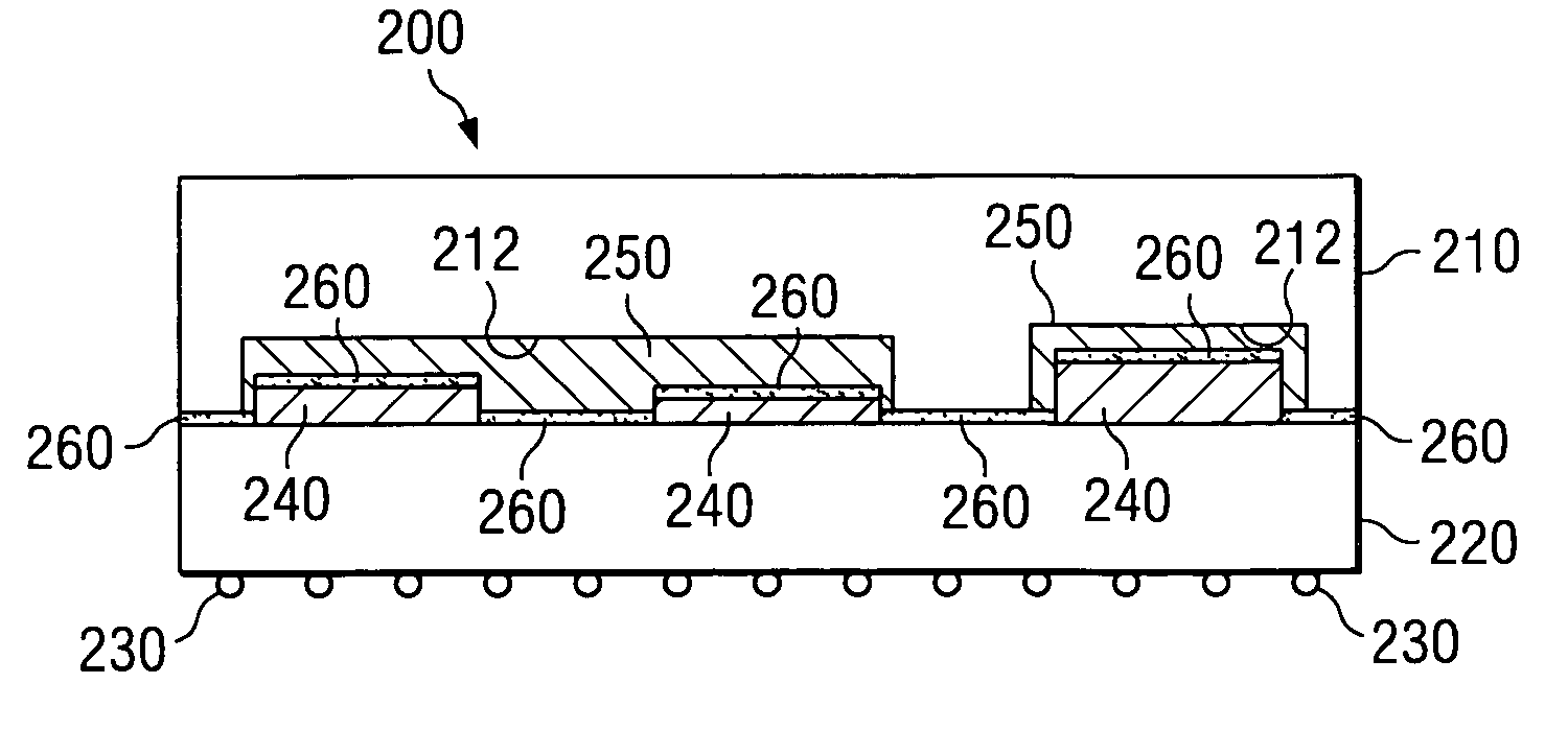
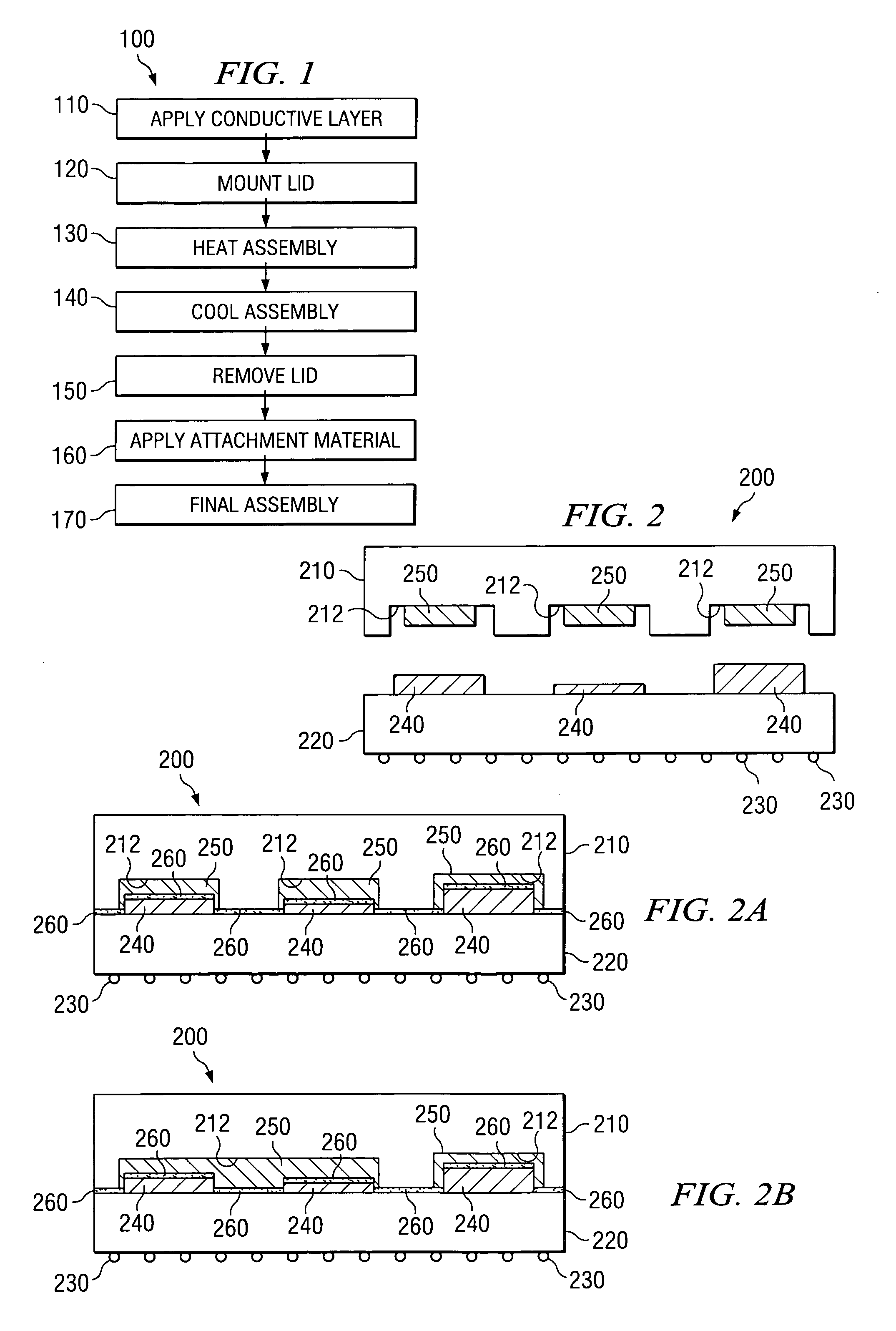
[0011]Multi-chip modules (MCMs) are semiconductor devices with more than one die mounted on a substrate. During operation, these semiconductor devices generate heat that must be dissipated to allow the semiconductor device to continue functioning properly. Accordingly, current methods of heat dissipation include mounting a lid having cavities with substantially uniform dimensions corresponding to each die on the substrate. This lid or heat sink is generally mounted to the substrate so that the individual dies of the semiconductor device fit inside the cavities of the lid. Often, the individual dies on the substrate of an MCM or ASIC have varying heights and dimensions, thus resulting in gaps of varying sizes between the dies and the surface of the lid cavities. In order to dissipate heat from the dies to the heat sink link, epoxies are often used to fill the gaps between the dies and the cavity. Unfortunately, most epoxies have very poor thermally conductive properties. For example,...


PUM


Abstract

A custom-molded heat sink corresponds to an individual substrate and includes a heat sink lid having at least one cavity corresponding to at least one die mounted on a substrate. A conductive layer is deposited in the at least one cavity that substantially fills the space between the at least one cavity and the at least one die when the lid is coupled to the substrate.

Description

TECHNICAL FIELD OF THE INVENTION[0001]This invention relates generally to multiple chip devices, and more particularly to a system and method for removing heat from a multiple chip device.BACKGROUND OF THE INVENTION[0002]Multi-chip semi-conductor devices are generally manufactured by mounting multiple dies onto a substrate. Many of these dies are of different dimensions due to the different functions performed by the multi-chip devices. Accordingly, heat sinks manufactured to dissipate heat from the individual devices mounted on a substrate or a multi-chip module (MCM) or an application specific integrated circuit (ASIC) often have cavities corresponding to the number of devices mounted on any given MCM or ASIC, and are generally of uniform dimension.[0003]In order to conduct heat from the semi-conductor devices to the heat sink for dissipation, an epoxy is generally used to fill the space between individual dies on the substrate and the cavity interior. These epoxies generally have...

Claims


Application Information

Patent Timeline
Patent Type & Authority Patents(United States)
IPC IPC(8): H01L23/12H01L23/36H01L23/42
CPCH01L23/36H01L23/42H01L2924/15311H01L2924/16153
Inventor EDWARDS, DARVIN R.
Owner TEXAS INSTR INC
Why Eureka
Try Eureka