Carrier frequency compensation system and method

a carrier frequency compensation and carrier frequency technology, applied in the direction of resonant circuits using central processing units, pulse techniques, electrial characteristics varying frequency control, etc., can solve the problem that the frequency of reference oscillators tends to slowly drift over time, the modem cannot detect the digital data signal contained in the modulated carrier signal, and the operating range is still limited by certain design criteria. problem, to achieve the effect of minimizing communications outages

Inactive Publication Date: 2005-12-27
TRITON NETWORK SYST
View PDF4 Cites 20 Cited by
  • Summary
  • Abstract
  • Description
  • Claims
  • Application Information

AI Technical Summary

Benefits of technology

[0013]The present invention provides a communication modem, terminal and / or system which automatically compensates for long-term drift of the frequency standards or references used by the transmitting and receiver terminals so as to avoid manual adjustment of the terminals to bring them back within operating tolerances and minimize communications outages caused by the inability of the system to otherwise accommodate for such drift. The invention is usable over a broad range of media including the microwave region of the electromagnetic spectrum.
[0022]According to another feature of the invention, the controller preferably provides the tuning signal so as to deterministically affect the comparison signal, e.g., minimize the value of the offset error signal. The phase-locked loop is operable over a predetermined range of signal frequencies on either side of a nominal center frequency while the controller calculates a number of discrete steps required to minimize the offset error signal.

Problems solved by technology

While the PLL can accommodate and adjust to some frequency variation of the reference signal, its operating range is still limited by certain design criteria.
If the difference between the local reference frequency and the received signal becomes too great, the PLL will unlock and the modem will be unable to detect the digital data signal contained in the modulated carrier signal.
However, the frequencies of the reference oscillators tend to slowly drift over time due to various factors, including component aging.
However, as the frequency drift between the terminals becomes more severe, the ability of the receiving PLL to retain a lock on the IF signal provided by radio circuitry 240 will be exceeded and the communications link will fail.
During this time, of course, the radio communications link is inoperative.

Method used


Image

  • Carrier frequency compensation system and method
  • Carrier frequency compensation system and method
  • Carrier frequency compensation system and method

Examples


Embodiment Construction

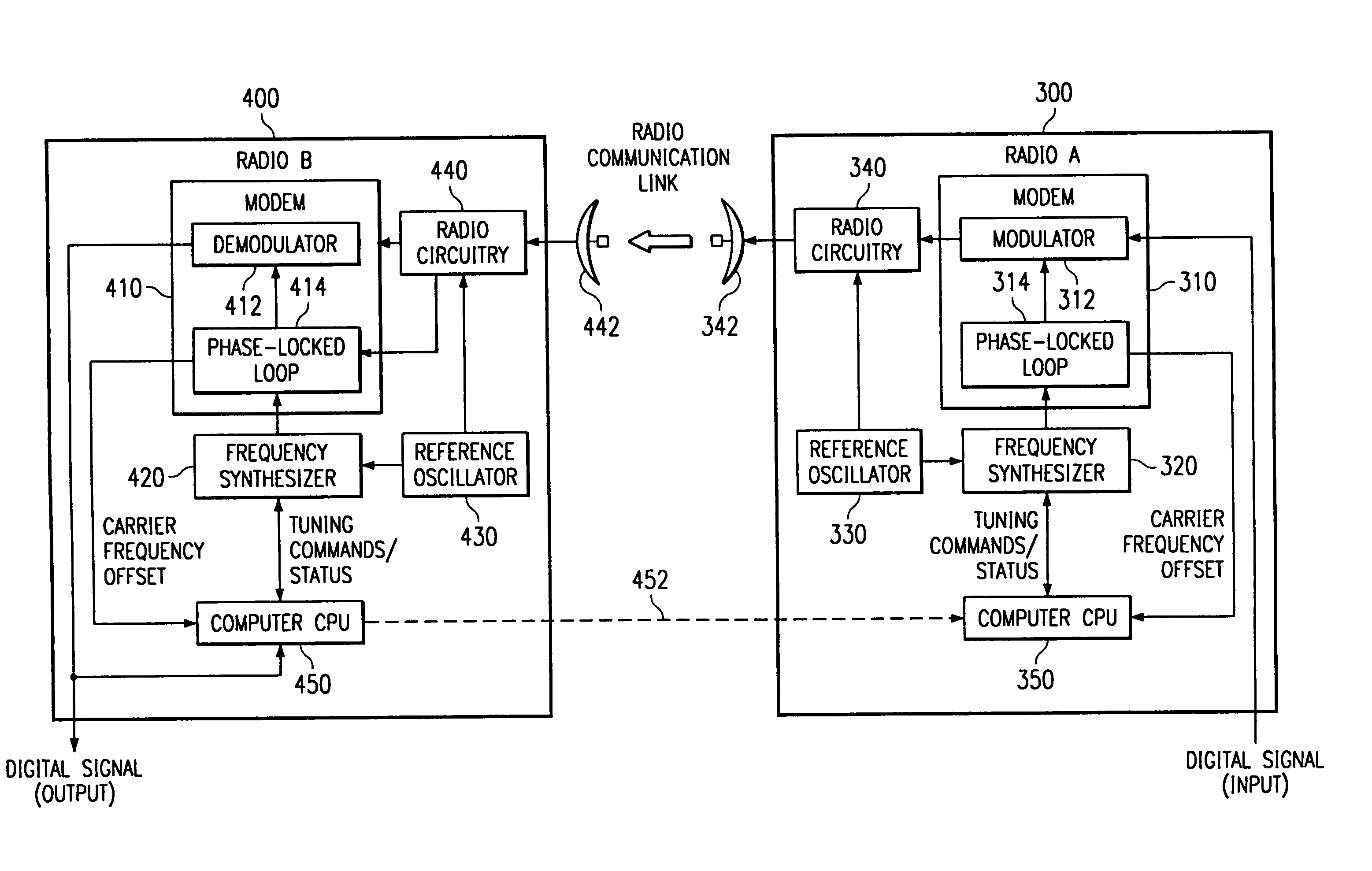
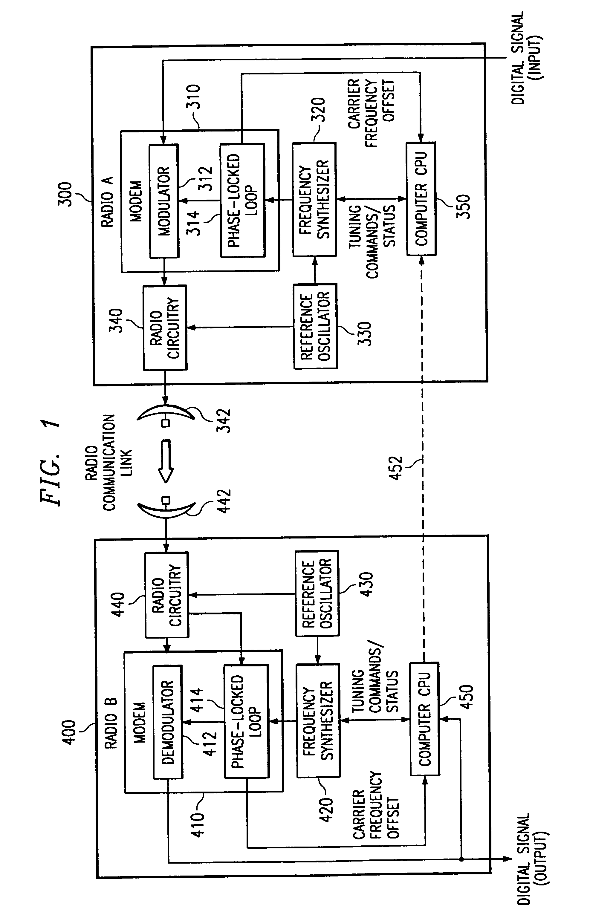
[0038]FIG. 1 is a block diagram of a point-to-point microwave radio system according to a preferred embodiment of the invention for transmitting information in the form of a data signal from a transmitter site A to a receiver site B. Typically the data signal is in the form of a digital data stream. The system preferably works in the 38 GHz range but is equally applicable to other frequencies, modes, and media of data transmission wherein receiver and transmitter facilities use distinct clock or frequency references which may drift with respect to each other, degrading or entirely inhibiting link performance. For simplicity of explanation, the embodiment of FIG. 1 is shown as a unidirectional system for the transmission of data from transmitter site A to receiver site B, although, as will be detailed later, the invention is equally applicable to bidirectional, full duplex radio links and similar media having the aforementioned requirement to maintain a precise carrier frequency betw...


PUM


Abstract

Systems and methods automatically compensate for long-term drift of frequency standards or references used by transmitting and receiver terminals to avoid manual adjustment of the terminals to bring them back within operating tolerances and minimize communications outages caused by inability of the system to otherwise accommodate for such drift. The present invention may provide automatic band selection to maintain a modulated carrier within an operating range of an automatic frequency control or tracking capability of a communication device. This may be accomplished by selecting an appropriate reference signal used to control a center frequency of an automatic frequency control circuit (such as a PLL) or used to convert the carrier frequency of the modulated carrier to fall within the operating range of the automatic frequency control circuit and / or by causing the transmitting station to at least partially correct the frequency discrepancy.

Description

REFERENCE TO RELATED APPLICATIONS[0001]Reference is made to the following and commonly assigned U.S. patent application entitled COMMERCIAL NETWORK BASED ON POINT TO POINT RADIOS, Ser. No. 09 / 245,701, filed Feb. 6, 1999, and which issued as U.S. Pat. No. 6,366,584 on Apr. 2, 2002, the disclosure of which is incorporated herein by reference.TECHNICAL FIELD[0002]The present invention relates generally to point-to-point microwave communication systems and, more particularly, to an apparatus and method for compensating for long-term frequency drift between radio sites.BACKGROUND[0003]Point-to-point microwave radio systems are widely used to transmit data between and among two nodes of a communication link. The microwave radio system includes microwave receivers and transmitters at both nodes of the system for transmitting and receiving data. Typically, data is received by a modem which modulates the data onto a baseband or intermediate frequency (IF) signal which is then up-converted to...

Claims


Application Information

Patent Timeline
Patent Type & Authority Patents(United States)
IPC IPC(8): H03J1/00H03J7/06H04B1/38H04L5/16H04L27/00H04L27/227
CPCH03J1/005H03J7/065H04L27/0014H04L27/2272H04L2027/0018H04L2027/0028H04L2027/0053
Inventor BABB, ROGER A.KRIZMAN, KEVIN J.
Owner TRITON NETWORK SYST
Why Eureka
Try Eureka