System and user interface for producing acoustic response predictions via a communications network

a communication network and acoustic response technology, applied in the field of loudspeaker system design, can solve the problems of complex calculations, system designers and acousticians that cannot find the benefits of acoustic prediction programs, and the design of a system that optimally performs in a given venue, so as to minimize local system requirements and minimize communication

Inactive Publication Date: 2005-12-01
MEYER SOUND LABORATORIES
View PDF2 Cites 13 Cited by
  • Summary
  • Abstract
  • Description
  • Claims
  • Application Information

AI Technical Summary

Benefits of technology

[0009] It is therefore a primary object of the present invention to provide a web hosted system and user interface which gives audio professionals access to complex acoustic prediction programs and the substantial processing power necessary to perform acoustic prediction calculations.
[0011] It is a further object of the invention to provide a web hosted acoustic prediction system which minimizes the local system requirements and which minimizes communications between the client and host computers.

Problems solved by technology

Designing a system that optimally performs in a given venue is a complex task, involving evaluation of the acoustic environment, equipment selection, and loudspeaker placement and equalization.
However, the benefits of acoustic prediction programs are not widely available to systems designers and acousticians due to the substantial computer and processing power required for these programs.
Acoustic analysis and prediction involves complex calculations using large amounts of data making stand-alone applications out of the reach of most designers.
Such prediction calculations also depend on the availability of current and accurate performance data for the loudspeakers to be used in the loudspeaker system design, data that is often unavailable to the designer on a timely basis, making acoustic predictions on a time critical project impractical.

Method used


Image

  • System and user interface for producing acoustic response predictions via a communications network
  • System and user interface for producing acoustic response predictions via a communications network
  • System and user interface for producing acoustic response predictions via a communications network

Examples


Embodiment Construction

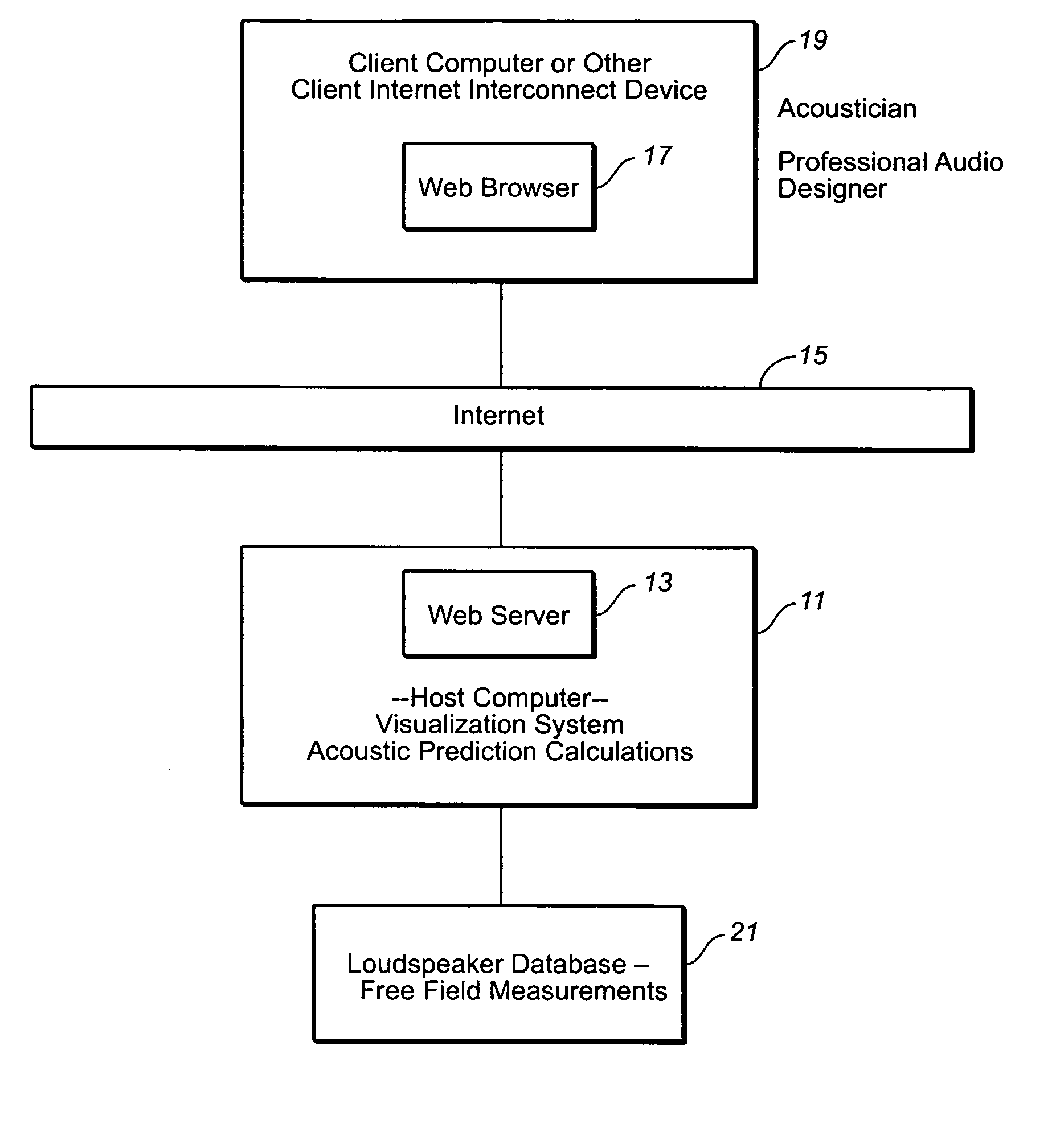
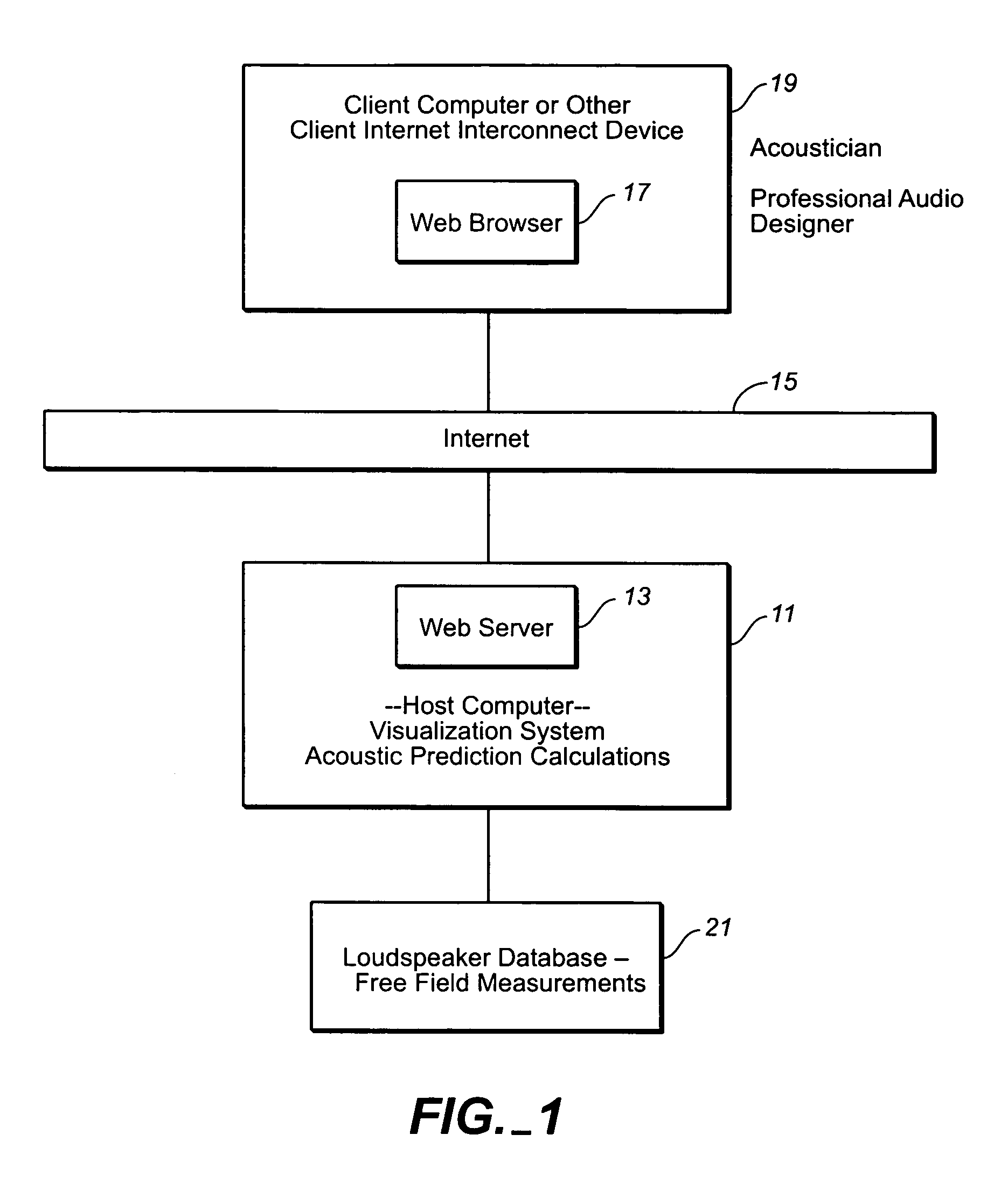
[0035] Referring to FIG. 1, the web hosted system of the invention is comprised of a host computer 11 having a web server 13 which communicates over the Internet (represented by block 15) with the web browser 17 of a client computer 19 operated by an audio professional such as an acoustician or professional audio designer. The host computer will have sufficient processing and storage resources to perform acoustic prediction calculations based on input parameters sent to it by the client computer via the client computer's web browser. The size and system requirements for the host computer will be selected based on the system capabilities desired, the sophistication of the acoustic prediction program used, and data storage requirements. A loudspeaker database 21 contained within or accessible to the host computer is provided to provide the host computer with acoustic performance data for selected loudspeaker models on which acoustic predictions are based. Preferably, the loudspeaker d...


PUM


Abstract

A web hosted system and user interface in a client-server architecture permits audio designers to perform acoustic prediction calculations from a thin client computer. A client computer or other Internet connect device having a display screen is used by an audio professional to access via the Internet a host computer which performs acoustic prediction calculations and returns results of the calculations to the client. The results of the calculations are returned in the form of data visualizations, such as an area view showing visualizations of sound pressure levels within a defined space, an impulse view showing the time domain response at a defined location, and / or a frequency domain view showing the frequency response at a defined location. Calculations are performed based on user-defined inputs, such as speaker type and location, sent to the host computer from the client computer and based on retrieval of loudspeaker data from one or more databases accessible by the host computer.

Description

CROSS-REFERENCE TO RELATED APPLICATIONS [0001] This is a continuation of U.S. application Ser. No. 09 / 963,095 filed Sep. 24, 2001, which claims the benefit of U.S. Provisional Application No. 60 / 234,738 filed Sep. 22, 2000.BACKGROUND OF THE INVENTION [0002] The present invention generally relates to loudspeaker system design and more particularly to providing acoustic predictions for modeled loudspeaker system designs before the actual implementation of the designs. [0003] Loudspeaker systems are used for sound re-enforcement in a wide variety of indoor and outdoor venues, ranging from small nightclubs to large concert halls and outdoor arenas. Designing a system that optimally performs in a given venue is a complex task, involving evaluation of the acoustic environment, equipment selection, and loudspeaker placement and equalization. Computer programs exist for performing acoustic predictions to assist designers and acousticians in designing optimum systems for a particular acousti...

Claims


Application Information

Patent Timeline
Patent Type & Authority Applications(United States)
IPC IPC(8): G10L11/00H04R9/06H04R29/00
CPCH04R29/008H04R29/007
Inventor MEYER, JOHN D.MEYER, PERRINSCHMIEDER, MARK
Owner MEYER SOUND LABORATORIES
Why Eureka
Try Eureka