Space reuse during technology upgrade in a protection area of an outdoor enclosure

a technology for outdoor enclosures and protection areas, applied in the direction of optical light guides, fibre mechanical structures, instruments, etc., can solve the problems of insufficient space for dsl equipment in the current cabinet, and the inability of companies to install additional cabinets, etc., to achieve easy identification of line cards to be replaced and compact arrangement

Inactive Publication Date: 2005-12-27
WHITE OAK GLOBAL ADVISORS
View PDF17 Cites 283 Cited by
  • Summary
  • Abstract
  • Description
  • Claims
  • Application Information

AI Technical Summary

Benefits of technology

[0012]In one specific embodiment, a protect block is replaced (in a one-for-one manner) with a fiber fanout enclosure that holds adapters for connectors of optical fibers. The protect block and the fiber fanout enclosure are designed to have approximately (or even exactly) the same footprint, so that they occupy at least some of the same space (before and after replacement). Reuse of the same space in this manner is advantageous over a telecommunication enclosure that is designed to have additional space dedicated for adapters and fiber fanout enclosures to be added in future, because of a more compact arrangement resulting from reuse of the same space. Moreover, in some embodiments, there is a one-to-one correspondence between a copper line card and its corresponding protect block, and during migration from copper to fiber, the correspondence is maintained so that identification of line cards to be replaced is easy.

Problems solved by technology

However, cabinets that currently house such DLCs and NGDLCs often lack sufficient space for DSL equipment.
Right-of-way issues, aesthetics and high costs (e.g. in pouring new concrete pads or installing additional poles, and obtaining additional electrical power) discourage local telephone companies from installing additional cabinets to support DSL services.

Method used


Image

  • Space reuse during technology upgrade in a protection area of an outdoor enclosure
  • Space reuse during technology upgrade in a protection area of an outdoor enclosure
  • Space reuse during technology upgrade in a protection area of an outdoor enclosure

Examples


Embodiment Construction

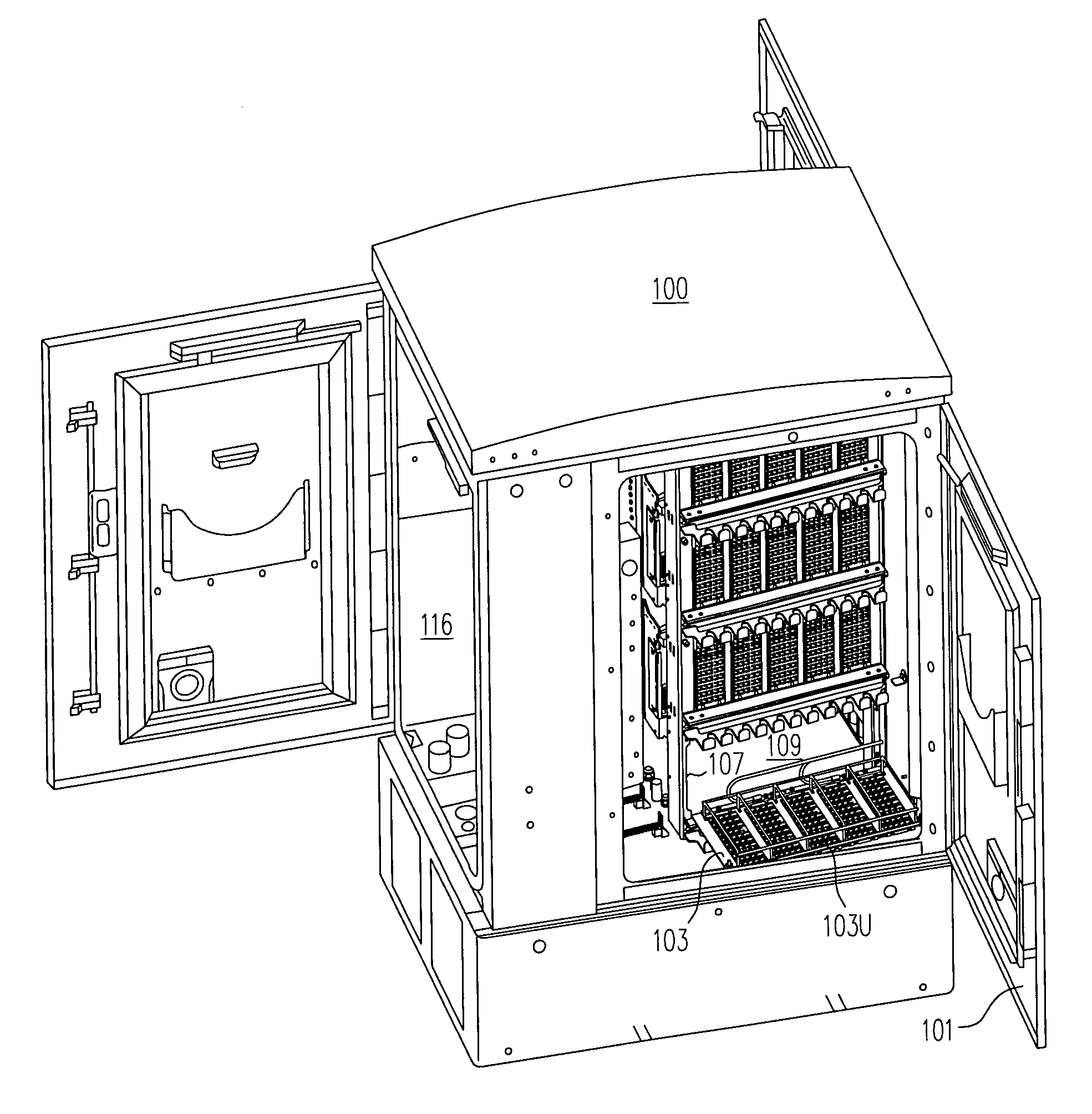
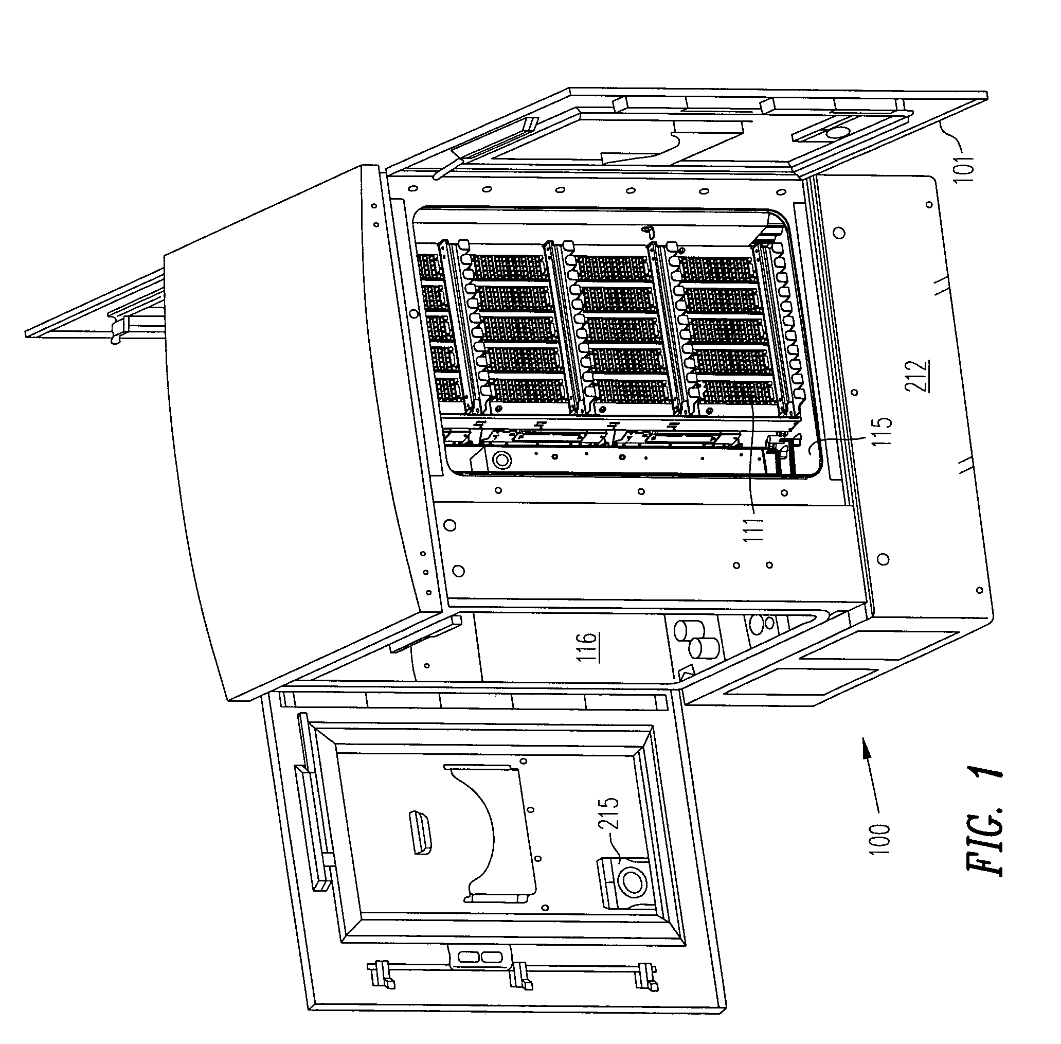
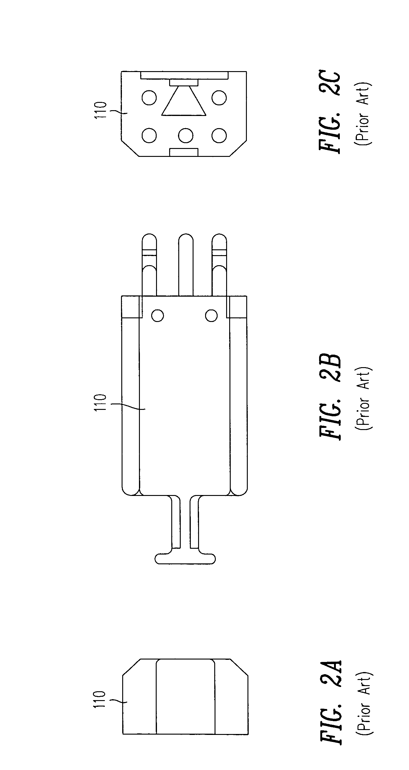
[0027]An outdoor enclosure 100 (FIG. 1) for a remote terminal is designed in accordance with the invention so that a block 111 (FIG. 1) supporting one or more protector modules 110 (FIG. 2) normally coupled between telephone lines and line cards (to prevent damage from a sudden fluctuation in current or voltage) is easily reachable and removable. For example, block 111 (called “protect block”), in enclosure 100 may be accessed simply by opening a door (also called “rear door”) 101 of a compartment (also called “protection compartment”) 115 located in the rear of outdoor enclosure 100.

[0028]In one example, protect block 111 is two line cards wide, and supports up to 48 telephone lines (with 24 telephone lines going into each line card). Protect block 111 can be, for example, part number P67304, P66894 or P67417 available from Marconi (Reltec). The protector modules can be any vendor's standard UL approved 5 pin protectors, for example, Joslyn Hi-Voltage Corporation (216) 271-6600's p...


PUM


Abstract

An outdoor enclosure for a remote terminal is designed so that a structure supporting protector modules (normally coupled between telephone lines and line cards to prevent damage from a surge in current or voltage) is easily reachable and removable. To upgrade from copper to fiber, the just-described hardware (also called “protect block”) is replaced with other hardware (also called “fiber fanout enclosure”) that supports adapters for receiving connectors of optical fibers. The protect block and the fiber fanout enclosure are designed to have approximately (or even exactly) the same footprint, so that they occupy at least some of the same space (before and after replacement). Reuse of the same space in this manner is advantageous over an outdoor enclosure designed to have additional space dedicated for adapters and fiber fanout enclosures to be added in future, because a more compact arrangement results from reuse of the same space.

Description

CROSS-REFERENCE TO RELATED APPLICATIONS[0001]This application is related to and incorporates by reference herein in their entirety the following commonly owned, U.S. patent applications:[0002]Ser. No. 10 / 081,672, entitled “Beverage Holder Tray On Outdoor Enclosure” by Jane Rodgers filed on Feb. 21, 2002;[0003]Ser. No. 09 / 814,024, entitled “Heat Exchanger” by Paul D. Swieconek filed on Mar. 21, 2001; and[0004]Ser. No. 10 / 081,469, entitled “Removable Bracket For A Backplane” by Matthew K. Meeker filed on Feb. 21, 2002.[0005]This application is also related to and incorporates by reference herein in its entirety a concurrently filed patent application, U.S. application Ser. No. 10 / 137,131, entitled “Space Reuse During Technology Upgrade In A Cable Splice Area Of An Outdoor Enclosure” by Paul D. Swieconek.BACKGROUND[0006]Network elements are commonly used in a telecommunication network to transfer communication signals between various locations (such as cities or suburbs within a city)....

Claims


Application Information

Patent Timeline
Patent Type & Authority Patents(United States)
IPC IPC(8): G02B6/00G02B6/44
CPCG02B6/4452
Inventor SWIECONEK, PAUL D.
Owner WHITE OAK GLOBAL ADVISORS
Why Eureka
Try Eureka