Modular multi-stage fusing system

a multi-stage, fusing system technology, applied in the direction of electrographic process apparatus, instruments, optics, etc., can solve the problems of paper deformation, paper wrinkles, paper overfusing, etc., to improve the fusing effect, reduce the dwell time in nip, and prolong the life of parts

Inactive Publication Date: 2005-12-27
XEROX CORP
View PDF7 Cites 32 Cited by
  • Summary
  • Abstract
  • Description
  • Claims
  • Application Information

AI Technical Summary

Benefits of technology

[0016]There is a need for a fusing system that will provide longer dwell times for heavier weight substrates.
[0027]In exemplary embodiments, the fuser system allows for longer dwell time for heavy weight substrates.

Problems solved by technology

Too much energy applied to a light weight copy medium, such as, for example, paper, results in over-fusing of the paper and non-uniform cooling.
Over-fusing of the paper and / or non-uniform cooling results in paper deformation, paper wrinkle, and other print defects.
Further, too much energy may also result in difficulties in stripping the paper off the roll because the paper will become “flimsy” when overheated.
Application of more energy than required for a given print medium will also tend to negatively affect the quality of the toner.
This may further lead to contamination of the fusing system.
Not enough energy applied to a heavier weight copy medium, such as, for example card stock, will result in the toner image not being fully fused, causing print defects.
Heavy weight papers, especially smooth coated heavy weights, are proving to be difficult to fuse because so much energy is being put into the paper that gloss differential on the first side image in the paper of the pre-fuser transport occurs due to non-uniform cooling effects of the post fuser vacuum transport and pinch roller transports.
Further, increasing fuser nips and raising temperatures with thicker-coated rolls will not allow for medium to low beam strength copy mediums (i.e., light weight to medium weight mediums) to strip with primary fusing device 10.
With high gloss papers, too much energy applied to the paper will result in image artifacts, such as, for example, a false image of the post-fuser transport and pinch roller due to non-uniform cooling.
Further, to fuse a heavier weight substrate with merely a single fuser system, visible defects will result.
Further still, the light weight substrates will be compromised.
A single fuser operating space to achieve the performance goals on all substrates has not been possible.

Method used


Image

  • Modular multi-stage fusing system
  • Modular multi-stage fusing system
  • Modular multi-stage fusing system

Examples


Embodiment Construction

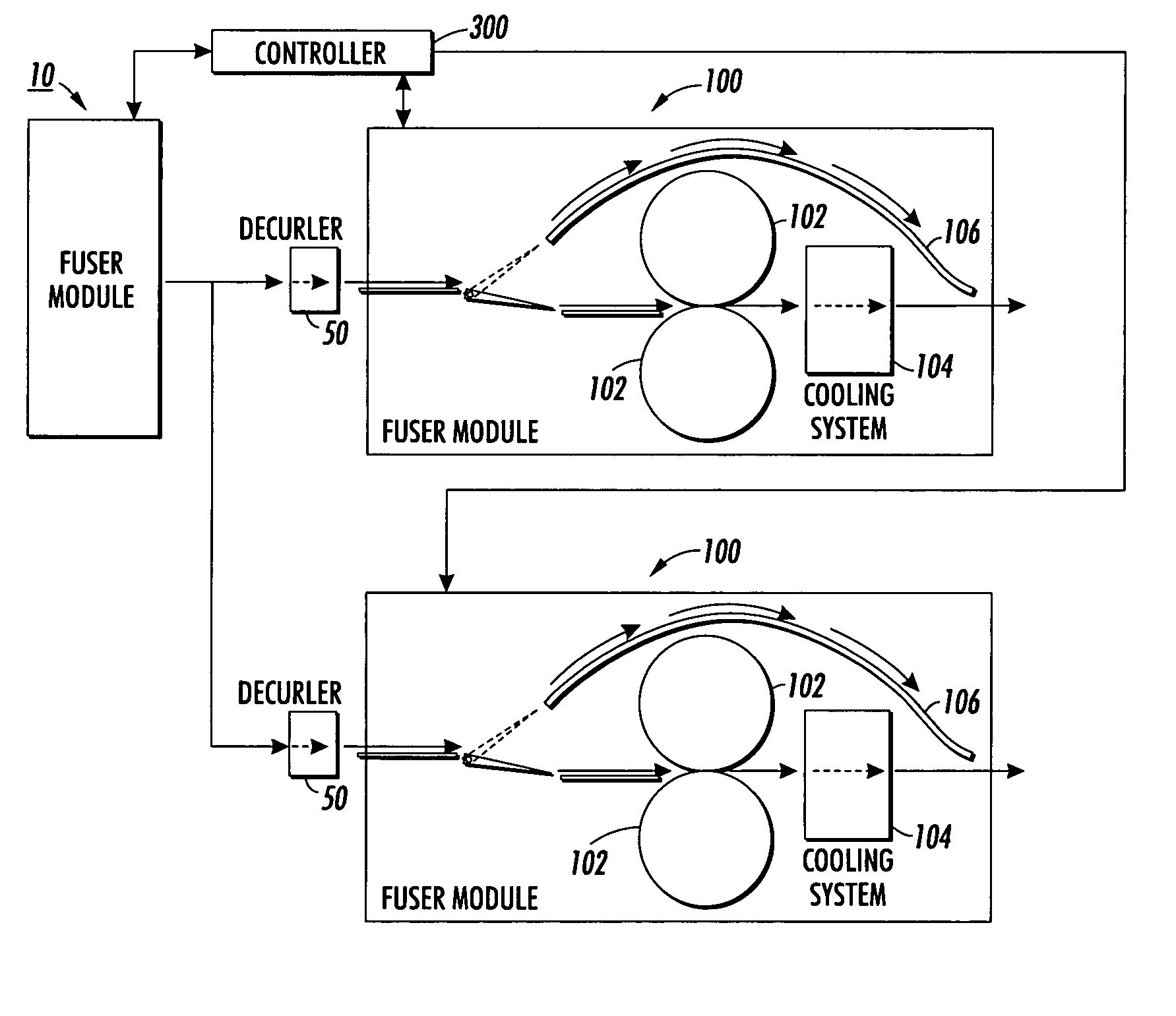
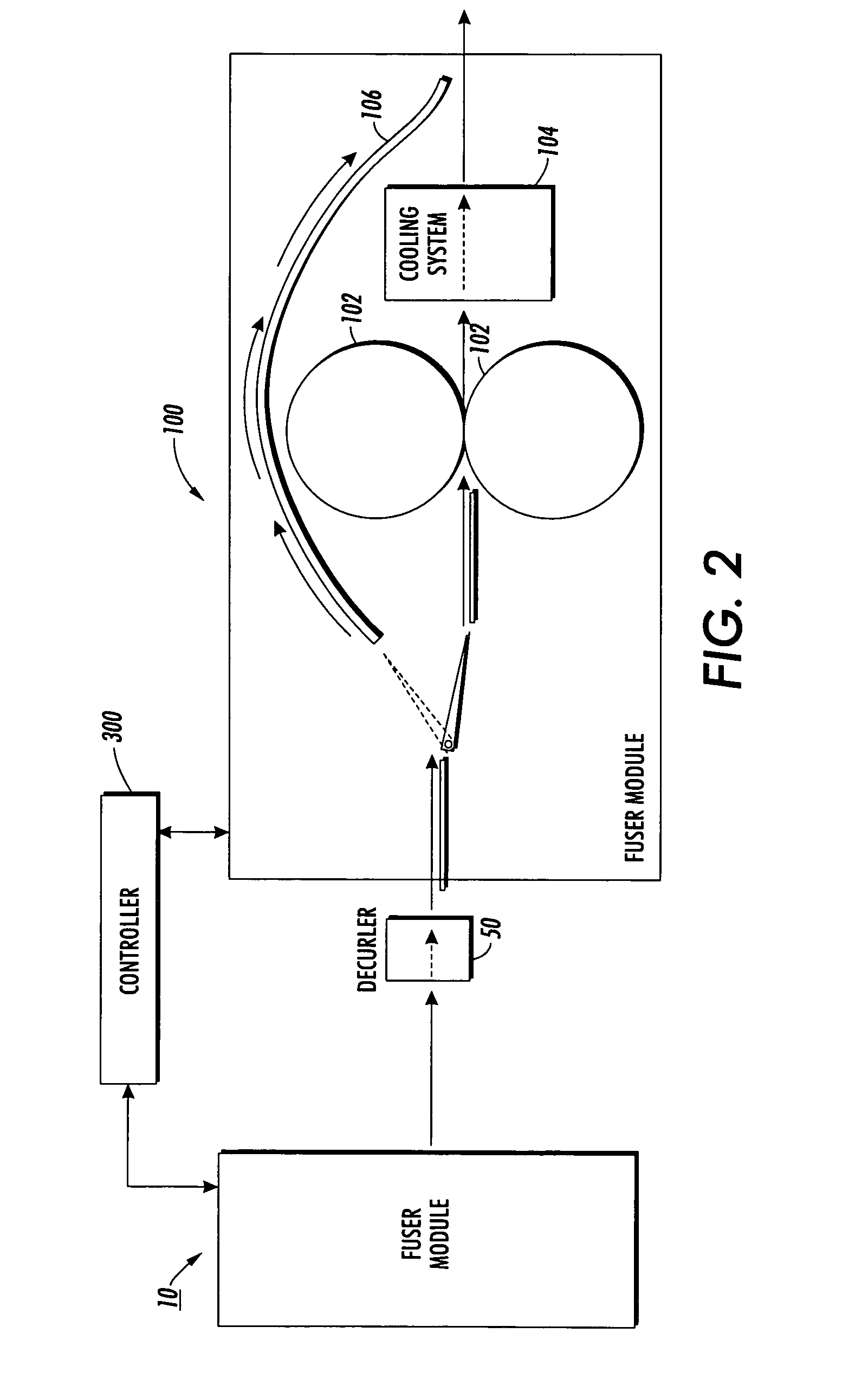
[0033]The present invention is a multi-stage fusing system which incorporates a primary fusing device of one configuration which is designed to operate with both simplex and duplex mode fusing to various paper substrates and capable of stripping the substrates, including light weight varieties, to deliver the prints to a separate fusing device downstream of the duplex paper path. The separate fusing device is herein referred to as a secondary fusing device.

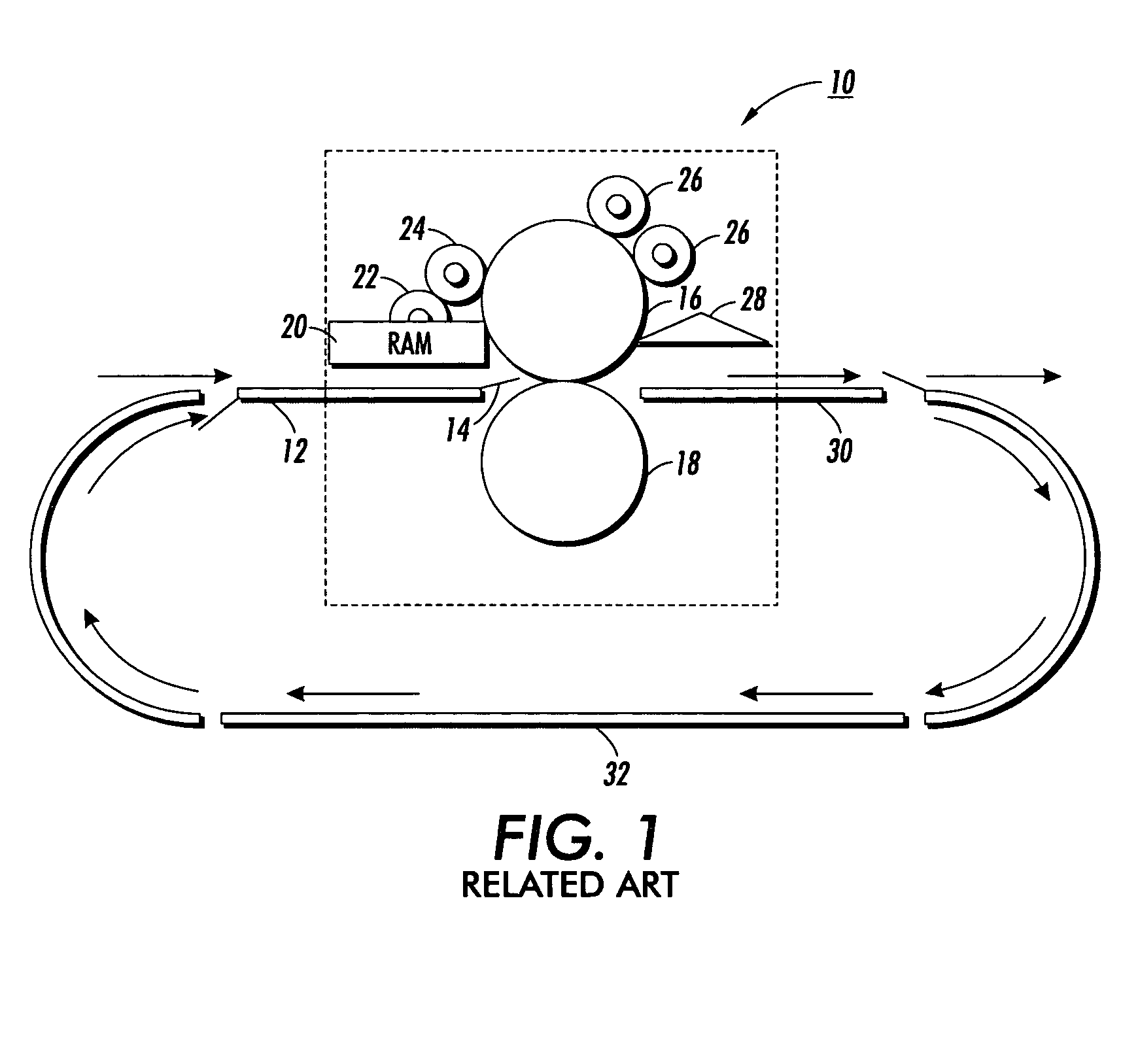
[0034]Referring to FIG. 1, a known primary fusing device 10 is illustrated. A copy medium or substrate, such as, for example, a sheet of paper (not shown), is fed to the primary fusing device 10 by a pre-fuser transport 12. More specifically, the pre-fuser transport 12 carries the substrate and a pre-fuser baffle 14 feeds the substrate between a fuser roll 16 and a pressure roll 18.

[0035]A release agent management system (RAM) 20 or chemically active fuser agent (not shown) supplies a coating of oil to the fuser roll 16. A meterin...


PUM


Abstract

A multi-stage fusing system for fixing toner images to copy substrates of various weights has a primary fuser and a secondary fuser in series with the primary fuser. Various weights of print substrates may have toner images fixed thereon by the primary fuser. The various print substrates are then transmitted to the secondary fuser or directly to a finishing area. The secondary fuser is designed specifically for heavier weight substrates and a bypass paper path is provided for allowing lighter weight substrates to bypass the secondary fuser.

Description

BACKGROUND OF THE INVENTION[0001]1. Field of Invention[0002]This invention relates generally to an electrophotographic copying apparatus, and more particularly, to the heat and pressure fixing of toner images formed on a copy substrate by direct contact with a heated fusing member.[0003]2. Description of Related Art[0004]In the process of xerography, a light image of an original to be copied is typically recorded in the form of a latent electrostatic image upon a photosensitive member with subsequent development of the latent image by the application of marking particles commonly referred to as toner. The visual toner image is typically transferred from the member to a copy substrate, such as a sheet of plain paper, with subsequent affixing of the image by one of several fusing techniques.[0005]In one type of fusing system, a fuser roll is used which has an outer surface or covering of polytetrafluoroethylene or silicone rubber, the former being known by the trade name “Teflon”, to ...

Claims


Application Information

Patent Timeline
Patent Type & Authority Patents(United States)
IPC IPC(8): G03G15/20
CPCG03G15/2003
Inventor BOGOSHIAN, GREGORY V.
Owner XEROX CORP
Why Eureka
Try Eureka