Low-pressure airway management device with active coating and method for patient care

Inactive Publication Date: 2010-03-04
KIMBERLY-CLARK WORLDWIDE INC
View PDF2 Cites 14 Cited by
  • Summary
  • Abstract
  • Description
  • Claims
  • Application Information

AI Technical Summary

Benefits of technology

[0006]The present invention pertains to an improved a tracheal ventilating device that has a modified surface coating. The coated surface and the use of the d

Problems solved by technology

Hence, even if some of the fluids leak past the balloon cuff, the potential of causing an infection is reduced, thus res

Method used


Image

  • Low-pressure airway management device with active coating and method for patient care
  • Low-pressure airway management device with active coating and method for patient care
  • Low-pressure airway management device with active coating and method for patient care

Examples


Embodiment Construction

Section I.—Description

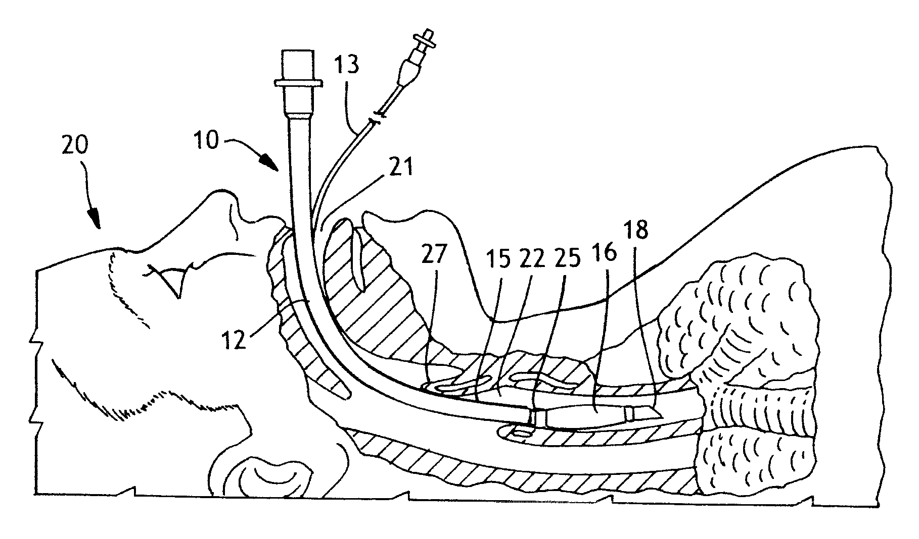
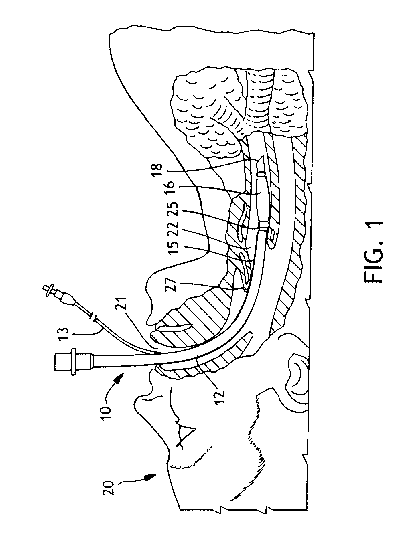
[0019]The present invention employs a multifunctional design approach that combines two or more functionalities to bring forth a synergistic effect to prevent aspiration of contaminated secretions, reduce colonization of the lower respiratory tract, and / or ultimately reduce the incidence of VAP. Specifically, by bringing together the features of an improved sealing cuff technology with subglottic suctioning and / or an eluting surface coating, one can achieve synergistic benefits in patient care and preventing aspiration of contaminated secretions. The invention, according to certain embodiments, builds upon the design and features of previous endotracheal tube designs, such as that described in U.S. Pat. Nos. 6,526,977 and 6,802,317, to F. Göbel, the contents of which are incorporated herein by reference. F. Göbel describes in the patents a tracheal tube having a cuffed balloon that obturates a patient's trachea as hermetically as possible. Attached to an air tu...


PUM


Abstract

An improved endotracheal tube that has a modified surface coating that can elute active agents is described. The coated surface and the use of the device according to a new method or regime for a healthcare worker to care for patients can help reduce the likelihood of ventilator acquire pneumonia or other infections in a patient's respiratory passages.

Description

FIELD OF INVENTION[0001]The present invention relates to a medical device that can be employed in patient airway management.BACKGROUND[0002]Patients requiring artificial respiration are often intubated with an endotracheal (ET) tube. As illustrated in FIG. 1, the tube is inserted into a patient's trachea in order to ensure that the airway is not closed off and that air is able to reach the lungs. The endotracheal tube is regarded as the most reliable available method for protecting a patient's airway.[0003]An ET tube is composed of two primary components: a hollow cannula or catheter (i.e., the tube), through which respiratory gasses pass, and a cuff, which serves to hold the catheter in place in the trachea, prevent air from bypassing the tube and, to a limited extent, prevent contaminants from entering the lower respiratory tract. The endotracheal tube functions as an artificial airway, allowing healthcare providers to mechanically ventilate the patient. While the ET tube serves a...

Claims


Application Information

Patent Timeline
IPC IPC(8): A61M16/04
CPCA61M16/04A61M16/0434A61M2025/0057A61M16/0479A61M2202/206A61M16/0443A61M2202/203
Inventor JENKINS, SHAWN E.TEIXEIRA, SCOTT M.MADSEN, EDWARD B.HOFFMAN, DOUGLAS R.AREHART, KELLY D.SMITH, MOLLY K.
Owner KIMBERLY-CLARK WORLDWIDE INC
Why Eureka
Try Eureka