

Liquid-cooled piston
a liquid-cooled piston and piston-pin technology, applied in trunk pistons, machines/engines, plungers, etc., can solve the problems of insufficient cooling of the piston-pin boss area, insufficient cooling of the surrounding area, and inability to meet the demands of strength, etc., to achieve the effect of easy production and strength demands
- Summary
- Abstract
- Description
- Claims
- Application Information
AI Technical Summary
Benefits of technology
Problems solved by technology
Method used
Image

Examples
Embodiment Construction
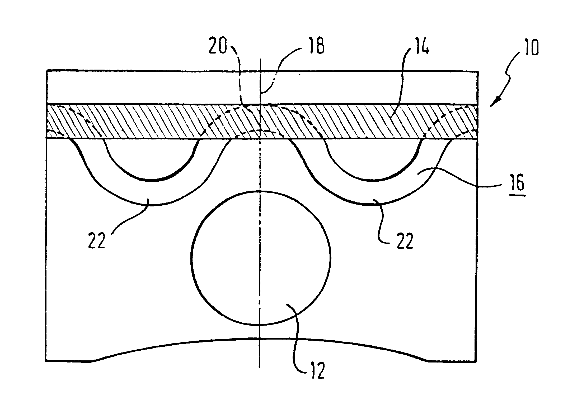
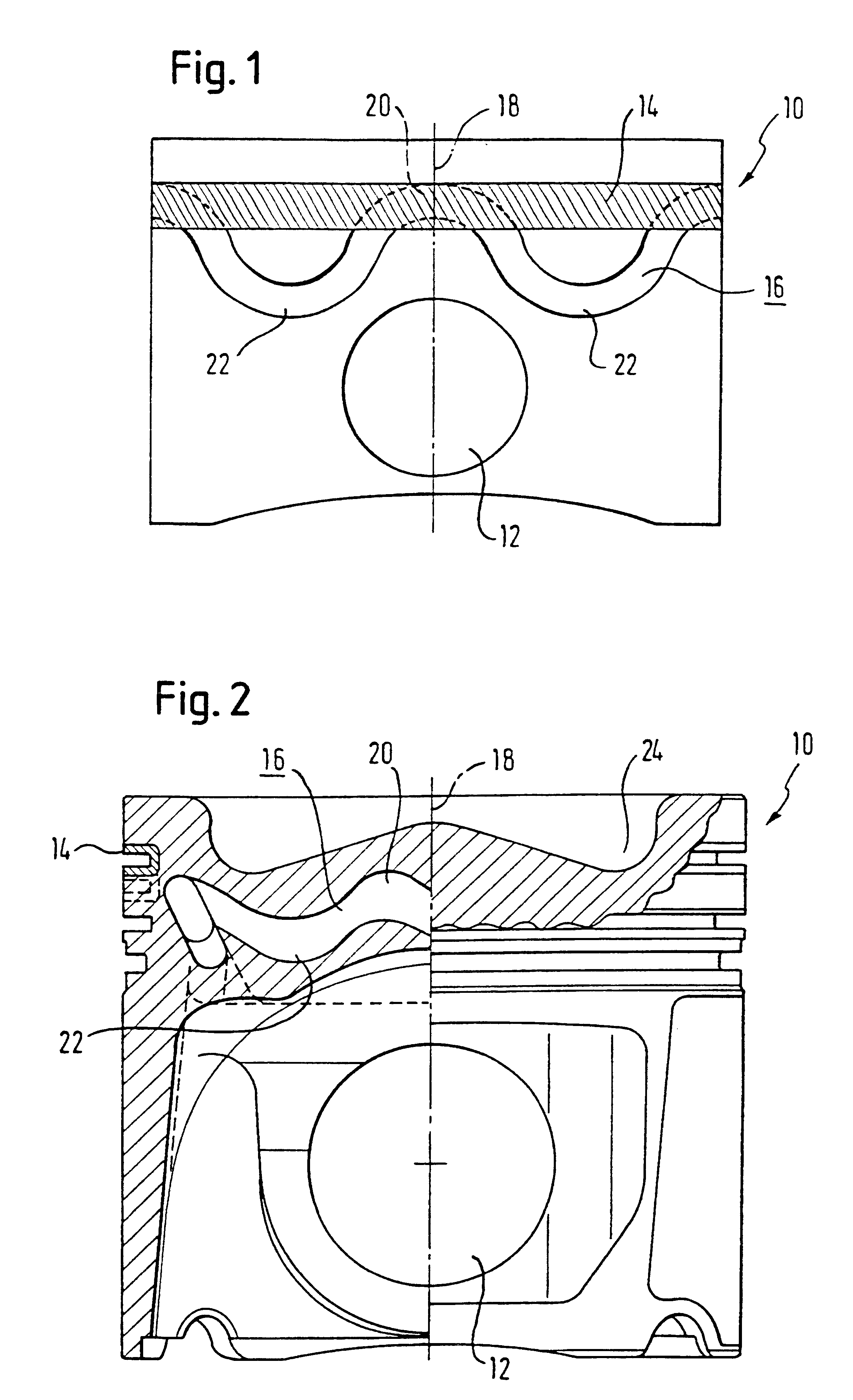
The object of the invention is to create a liquid-cooled piston which is easy to produce and which effectively cools the ring area as well as the piston-pin boss area, wherein the strength demands placed on the piston continue to be met.
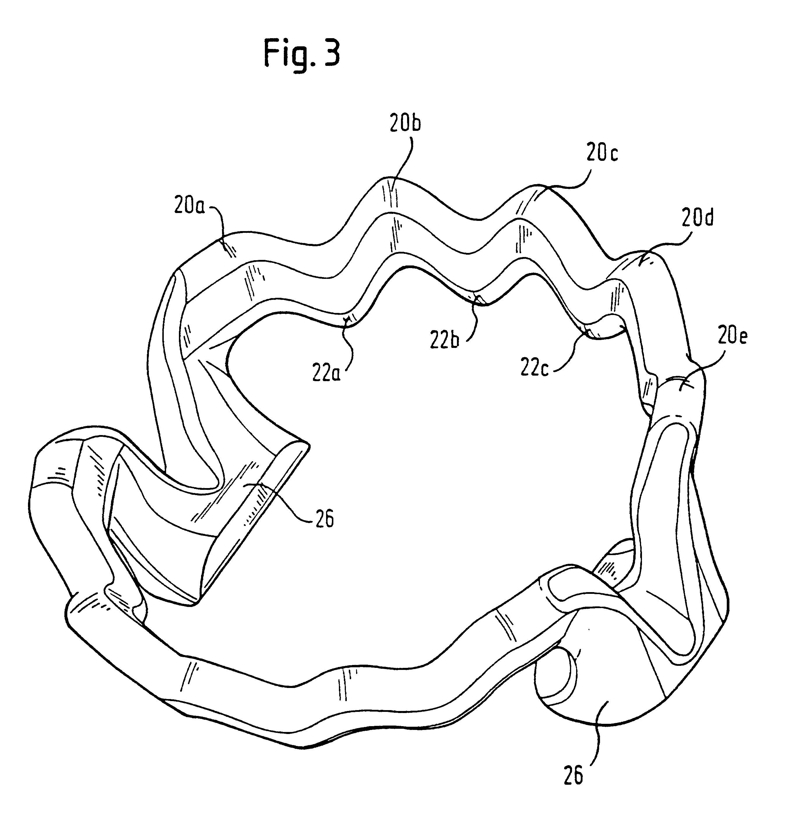
As a result, the cooling duct of the piston according to the invention which, when viewed as an entirety from above, has an extensive annular shape or consists of several annular segments which are designed in the direction of the axis piston in an undulated manner. Herein, the cross section of the cooling duct remains basically the same across the whole extent of the cooling duct, so that for example in contrast to the piston according to DE-PS 17 51 342, no unnecessary complication of the cooling duct design is required.
Rather the cooling duct extends with a substantially constant cross section in an undulated manner as seen in a side-view of the piston, so that it extends from the area behind the piston rings closer to the piston-pin boss in certa...
PUM
 Abstract
Description
Claims
Application Information