Cooler chest with radio

a technology of radio and cooler chest, which is applied in the direction of domestic cooling apparatus, electrophonic musical instruments, instruments, etc., can solve the problems of not being able to disclose the positioning or the size of such units, and achieve the effects of reliable energy source, convenient operation and protection from accidental damag

Inactive Publication Date: 2005-12-27
PEEPLES JASON W
View PDF11 Cites 27 Cited by
  • Summary
  • Abstract
  • Description
  • Claims
  • Application Information

AI Technical Summary

Benefits of technology

[0007]It is one aspect of the invention to utilize the lid or closure portion of commercially available cooler chests to house a complete radio receiver unit and power source. It is a second purpose of the invention that the radio and all related components and controls be sealed and maintained in a water proof condition. It is a third aspect of the invention that parts of the radio and related components are at least flush with the surfaces of the lid and are protected from accidental damaged. It is another aspect of the invention that the normal use of the cooler chest be maintained and that the radio be convenient to operate. It is still another aspect of the invention that a reliable source of energy be provided to operate the radio. It is still another aspect of the invention that various modifications will allow adaptation to a variety of commercially available cooler chests.

Problems solved by technology

Generally modifications have involved the chest or body portion of the cooler, or both the lid portion and the body, and modifications either expose functional components of the radio to mechanical or environmental damage or require significant modifications to commercially available cooler units.
In addition, the '912 patent suggests solar power units as sources of electrical power, but fails to disclose any positioning of such units or the size required.

Method used


Image

  • Cooler chest with radio
  • Cooler chest with radio
  • Cooler chest with radio

Examples


example 1

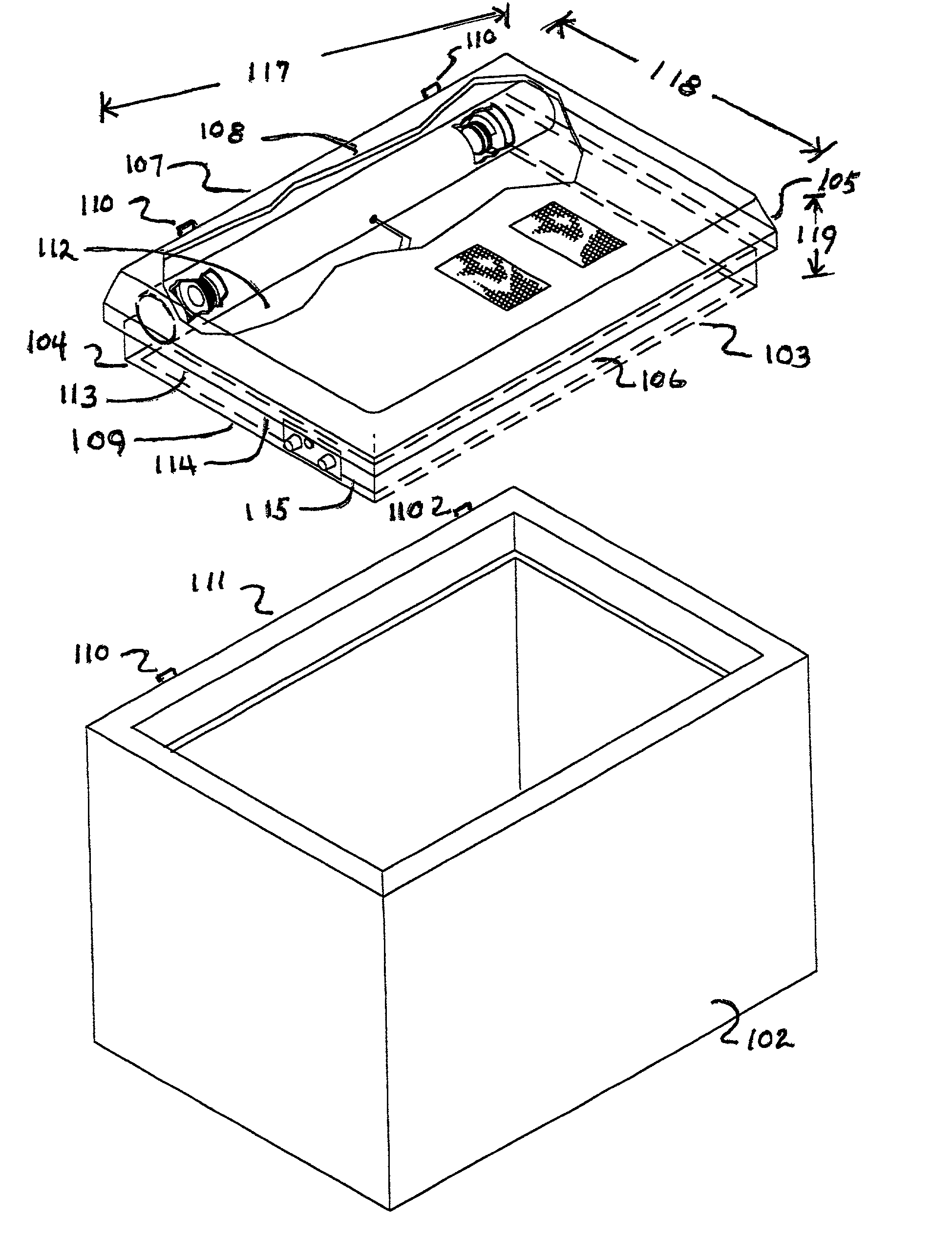
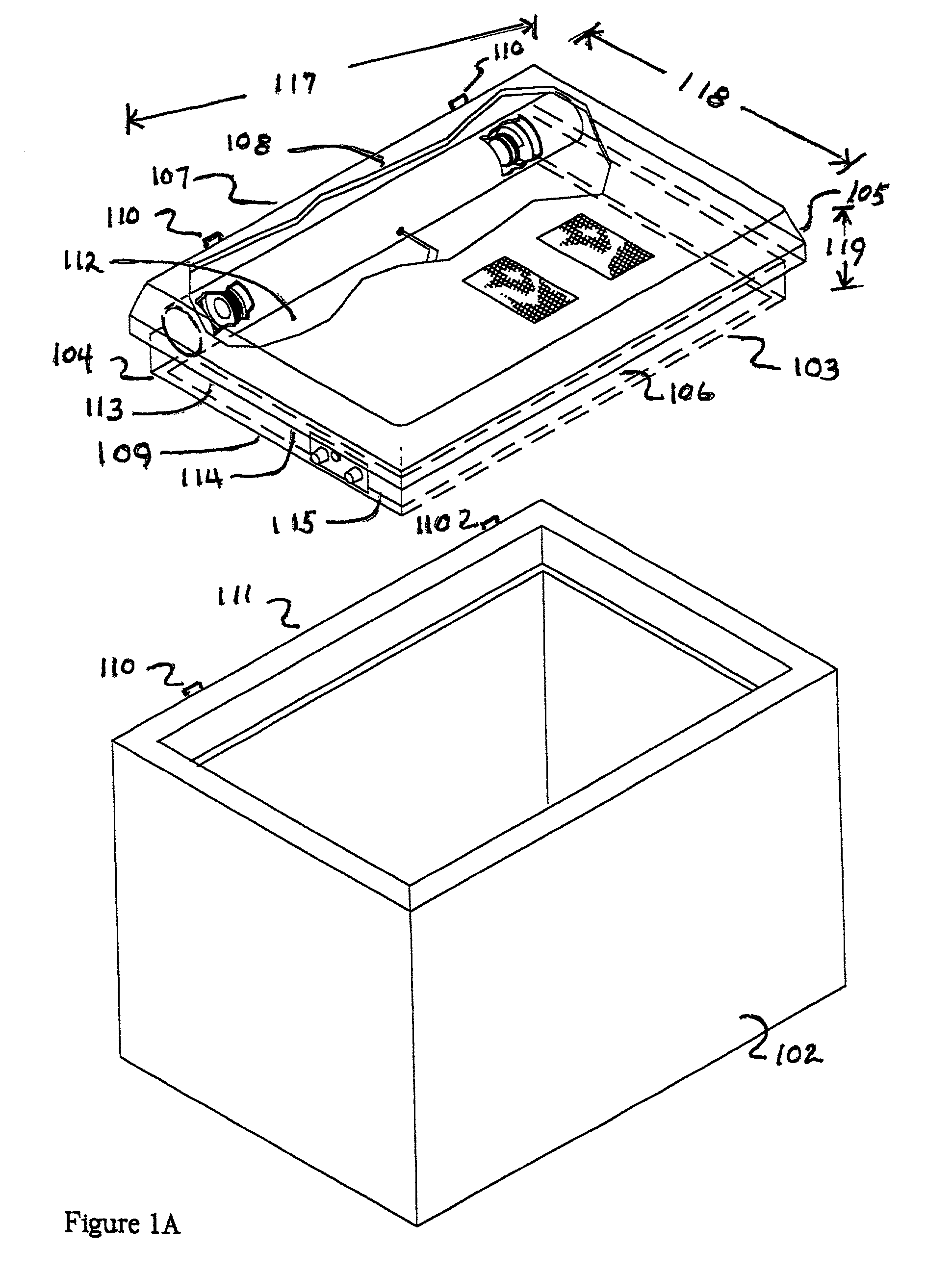
[0026]A preferred embodiment utilized a cooler chest having a rectangular lid with a flat surface and a hollow chamber as described in FIG. 1A. Outside dimensions of the lid of a commercially available cooler with this type of lid varied from a length of less than 60 cm (24 in) to over 120 cm (48 in), a width of less than 34 cm (13.25 in) to over 70 cm (27 in) and a primary height of less than 9.5 cm (4 in) to over 18 cm (8 in). The maximum diameter of the resonance chamber was determined by the primary height, and the maximum diameter of speakers was determined by the inside diameter of the resonance chamber. Within practical limits, sound quality improves with the size of speakers, thus maximum sizes of commercially available components and materials are used with in the limits set by the dimensions of the lid.

[0027]The inside length of the lid of a commercially available 54 quart capacity cooler was approximately 60 cm (24 in) and the primary height 9.5 cm (4 in). The primary hei...

example 2

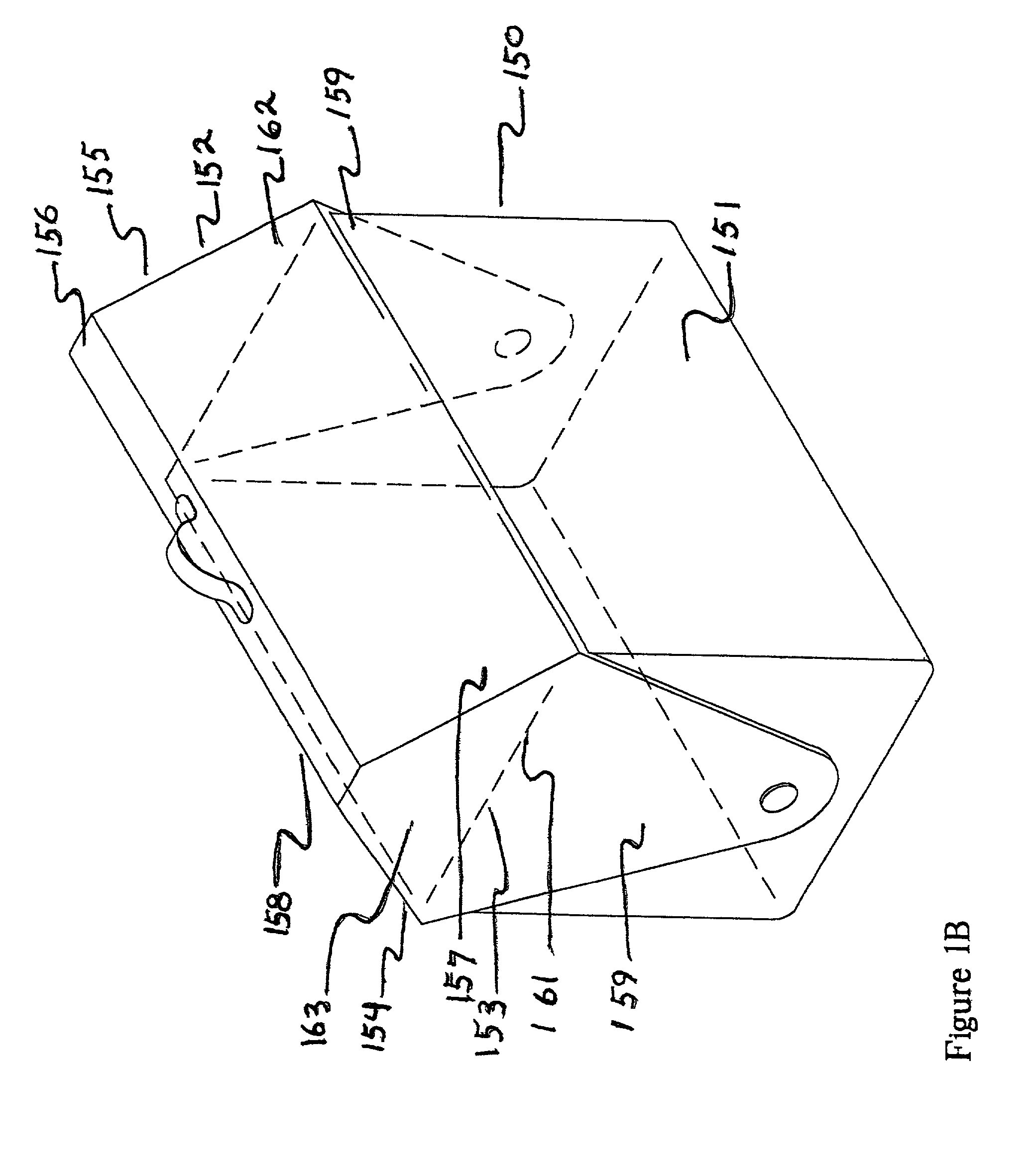
[0034]An alternate embodiment utilizes the coolers with lids shaped as described by FIG. 1B. In this embodiment, the resonance chamber is positioned longitudinally along the ridge. Depending on specific size considerations, windows for the solar panels may be positioned in both roof panels, and the open front box with batteries and controls positioned in a top panel or an end of the lid. The circuit board is also secured to a top panel by means of brackets to which the circuit board is attached. The basic design of the resonance chamber, wiring, and controls are unchanged from the Example 1.

example 3

[0035]An additional embodiment utilizes a cooler with a circular lid with a hollows chamber as described in FIG. 1A. One of average skill in the art recognizes that the resonance chamber can be readily positioned on any diameter line of the lid. Ends of the tube would require minimal additional fitting to fit the curve of the lid. In addition, the open face box as well as the windows may be positioned on the flat top of the lid.


PUM


Abstract

A resonance chamber with two or more speakers positioned in the lid of a commercially available cooler chest and electrically connected to a radio circuit board also positioned in the lid and powered by a solar panels or a combination of solar panels and batteries. All elements are water proofed and positioned for protection during normal use of the cooler and positioned so as to not disrupt the normal use of the cooler.

Description

FIELD OF THE INVENTION[0001]This invention is directed towards radios components powered by solar panels and positioned in the lid unit of various types of containers used for recreational and other purposes thereby enhancing the utility of the containers.BACKGROUND OF THE INVENTION[0002]For decades, the radio has been a source of entertainment, a significant element of many forms of recreation and a source of company for individuals in remote settings. The portable radio has evolved from a cumbersome, frequently fragile and less than dependable novelty to small, energy efficient, sturdy, dependable free standing units that accompany thousands as a significant part of outdoor recreational activities, including camping, picnicking, and similar, activities. In addition to size reduction and improved dependability plus transistor technology and the growth of circuit board technology, and the continued improvement of batteries, all have contributed to the seemingly ubiquitous presence o...

Claims


Application Information

Patent Timeline
Patent Type & Authority Patents(United States)
IPC IPC(8): F25D23/12H04B1/08
CPCF25D23/12H04B1/086F25D2331/804
Inventor PEEPLES, JASON W.
Owner PEEPLES JASON W
Why Eureka
Try Eureka