Flashing for an exterior arched surface and method

a technology of arched surface and flashing, applied in the field of exterior flashing, can solve the problems of rainwater traveling through the slits or cutouts, and slowly deteriorating when exposed to ultraviolet ligh

Inactive Publication Date: 2006-01-03
KJORSVIK DALE
View PDF12 Cites 26 Cited by
  • Summary
  • Abstract
  • Description
  • Claims
  • Application Information

AI Technical Summary

Benefits of technology

[0007]It is an object of the present invention to provide an attractive and paintable flashing for an arched wall projection.
[0008]It is another object of the present invention to provide such a flashing that prevents the intrusion of water.
[0009]It is a further object of the present invention to provide such a flashing when properly installed around an arched wall projection that does not deteriorate with exposure to ultraviolet radiation.
[0010]These and other objects of the present invention are met by a flashing specifically designed for use on an exterior arched wall projection that stops water intrusion and is resistant to damage caused by UV radiation. The flashing includes a Z-shaped or L-shaped body with a flexible flashing material adhesively attached to its back surface. In the preferred embodiment, the body includes a top flange member and an intermediate flange member. The top flange member is relatively wide and includes a plurality of transversely aligned slits evenly spaced thereon that allow the intermediate flange member to be bent around a curved or arched wall projection. In the preferred embodiment, the slits extend partially and transversely over the top flange member thereby leaving a small portion of the top flange member uncut. As the intermediate flange member is bent in a direction opposite the top flange member around an arched wall projection, the slits' opening widen so that the intermediate flange member may smoothly conform in shape to the adjacent arched wall projection. In a second embodiment, that flashing includes a lower flange member perpendicularly aligned with the intermediate flange member and opposite the top flange member. In both embodiments, flexible flashing material is adhesively bonded to the inside surfaces of the top, intermediate, and lower flange members and extends over the outside surface of the top flange member to completely cover the slits and the expanded slit openings. Because the top flange member is typically placed under wall siding, the section of flexible flashing material that covers the slits and slit openings is protected from ultraviolet radiation. The exposed portion of the top flange member is attractive and may be easily painted.

Problems solved by technology

One drawback with Z- or L-shaped flashing is that rainwater is able to travel through the slits or cutouts.
One drawback with flexible flashing material is that it slowly deteriorates when exposed to ultraviolet light.

Method used


Image

  • Flashing for an exterior arched surface and method
  • Flashing for an exterior arched surface and method
  • Flashing for an exterior arched surface and method

Examples


Embodiment Construction

)

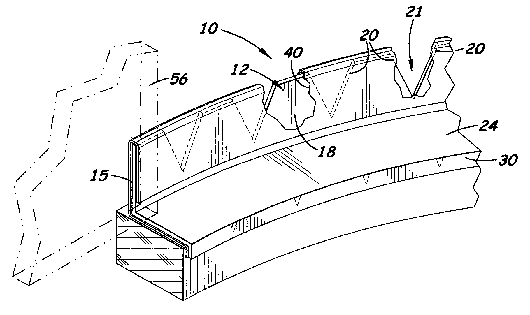
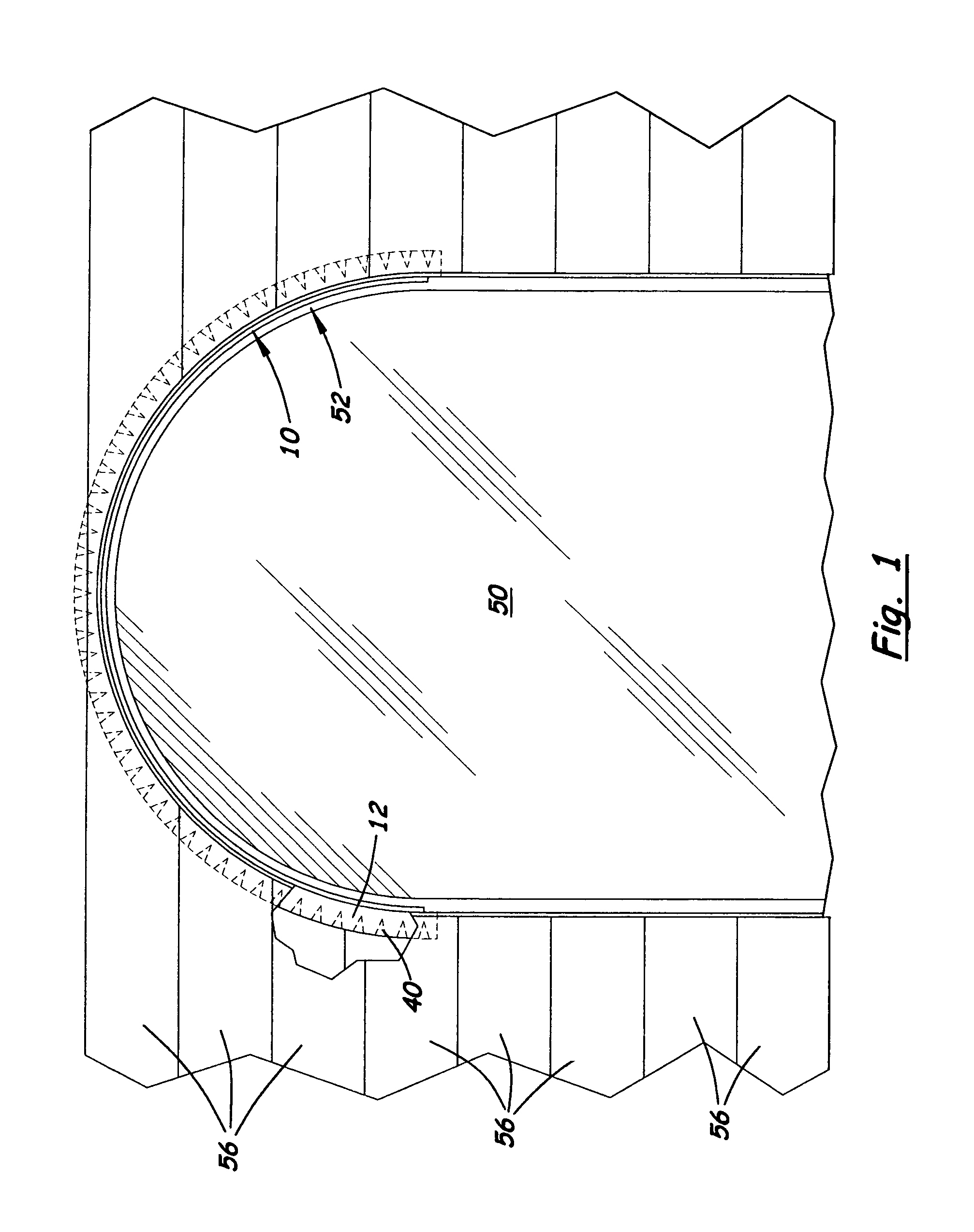
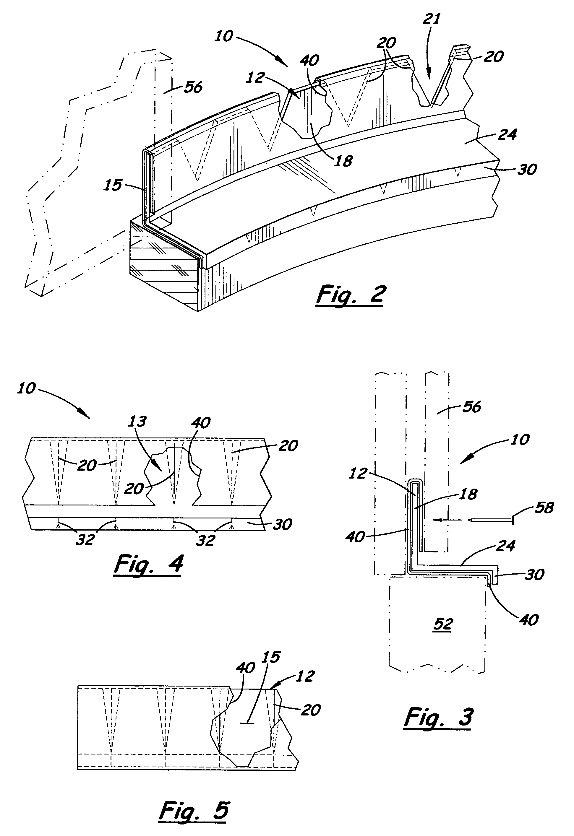
[0017]Shown in the accompanying FIGS. 1–5, there is shown a flashing 10 specifically designed for use on an exterior arched or curved wall projection 52 that stops water intrusion and provides a permanent, attractive, paintable surface that is safe from UV radiation. The flashing 10 includes a metal body 12 with flexible flashing material 40 bonded to its entire back surface 13 and a portion of its front surface 15. In the preferred embodiment, the metal body 12 is Z-shaped with top, intermediate and lower flange members 18, 24, 30, respectively. The top flange member 18 includes a plurality of transversely aligned slits 20 evenly spaced and formed thereon that allow the metal body 12 to be continuously bent in the direction toward the lower flange member 30 for placement around an existing curved or arched wall projection 52 commonly found around a window 50. The slits 20 are slightly shorter in length than the width of the top flange member 18 thereby creating a continuous, non-c...


PUM


Abstract

Flashing used on curved exterior wall projections designed to stop water intrusion and provide a permanent, attractive, paintable surface that is safe from UV radiation. The flashing includes a Z-shaped or L-shaped body bonded with a flexible flashing material along its front and back surface. The metal body includes at least two perpendicularly aligned flange members. Formed on the top flange member is a plurality of transversely aligned slits evenly spaced thereon that allow the flashing to be bent around a curved wall projection. The flexible flashing material is adhesively bonded to the inside and outside surfaces of the top flange member thereby covering the slits to create a water barrier. During installation, the top flange member and flexible flashing material are covered by external wallboards or siding.

Description

[0001]This is a utility patent application which claims benefit of U.S. Provisional Application No. 60 / 404,172 filed on Aug. 15, 2002.BACKGROUND OF THE INVENTION[0002]1. Field of the Invention[0003]This invention pertains to exterior flashing and, more particularly, to such flashing designed for use around curved exterior wall projections.[0004]2. Description of the Related Art[0005]Z- or L-shaped metal flashing is commonly used in the building industry to prevent the intrusion of water through a joint on an exterior wall projection, such as a windowsill or doorframe. Around curved exterior wall projections, slits or V-shaped cutouts are made on the flange members that enable the flashing to be bent around a curved surface. Also, flexible flashing made of rubber, latex, or asphalt-based material has been used that bends around a curved surface. One drawback with Z- or L-shaped flashing is that rainwater is able to travel through the slits or cutouts. One drawback with flexible flash...

Claims


Application Information

Patent Timeline
Patent Type & Authority Patents(United States)
IPC IPC(8): E04G15/02E04F19/02E06B1/00E06B1/62
CPCE04F19/02E06B1/62E06B1/006E04F2013/061
Inventor KJORSVIK, DALE
Owner KJORSVIK DALE
Why Eureka
Try Eureka