Linear actuators

a technology of actuators and actuators, applied in the direction of toothed gearings, valve details, belts/chains/gearrings, etc., can solve the problems of failure of fail-safe features, actuator reversal, and inability to meet the requirements of the actuator

Inactive Publication Date: 2006-01-03
BAKER HUGHES ENERGY TECH UK LTD
View PDF40 Cites 54 Cited by
  • Summary
  • Abstract
  • Description
  • Claims
  • Application Information

AI Technical Summary

Benefits of technology

[0014]Said torque reaction means is preferably such that it prevents rotation of said shaft during normal operation while said driven member is being moved from said first position to said second position but allows rotation of said shaft in the event of a fault so that said back-drive means can move the driven member to said first position.

Problems solved by technology

A hydraulic actuator normally comprises a simple piston and cylinder and has a fail-safe mechanism provided by the compression of a coil spring so that failure of the hydraulic power source results in the actuator reverting to its initial position by virtue of the potential energy in the spring returning the piston to its original position.
The disadvantage of an electric actuator as described above is that the fail-safe mechanism is not simple and has to reverse drive the actuator through its relatively complicated mechanism, which includes the motor, gearbox and rotary to linear mechanism.
Furthermore, any failure of the relatively complicated drive mechanism involving seizing or jamming will also result in failure of the fail-safe feature.
It is an additional problem that the provision of a fail-safe mechanism may prevent the actuator from being driven in both directions, ie extending and retracting.

Method used


Image

  • Linear actuators
  • Linear actuators
  • Linear actuators

Examples


Embodiment Construction

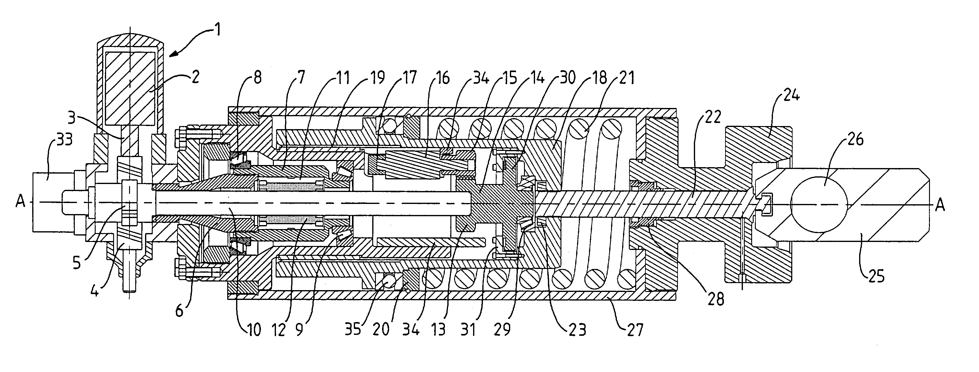
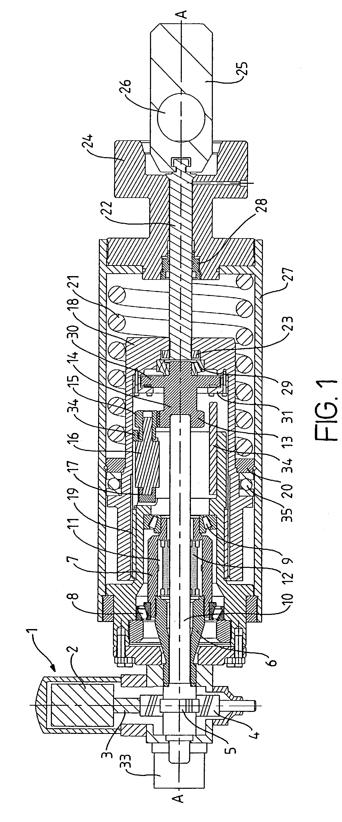
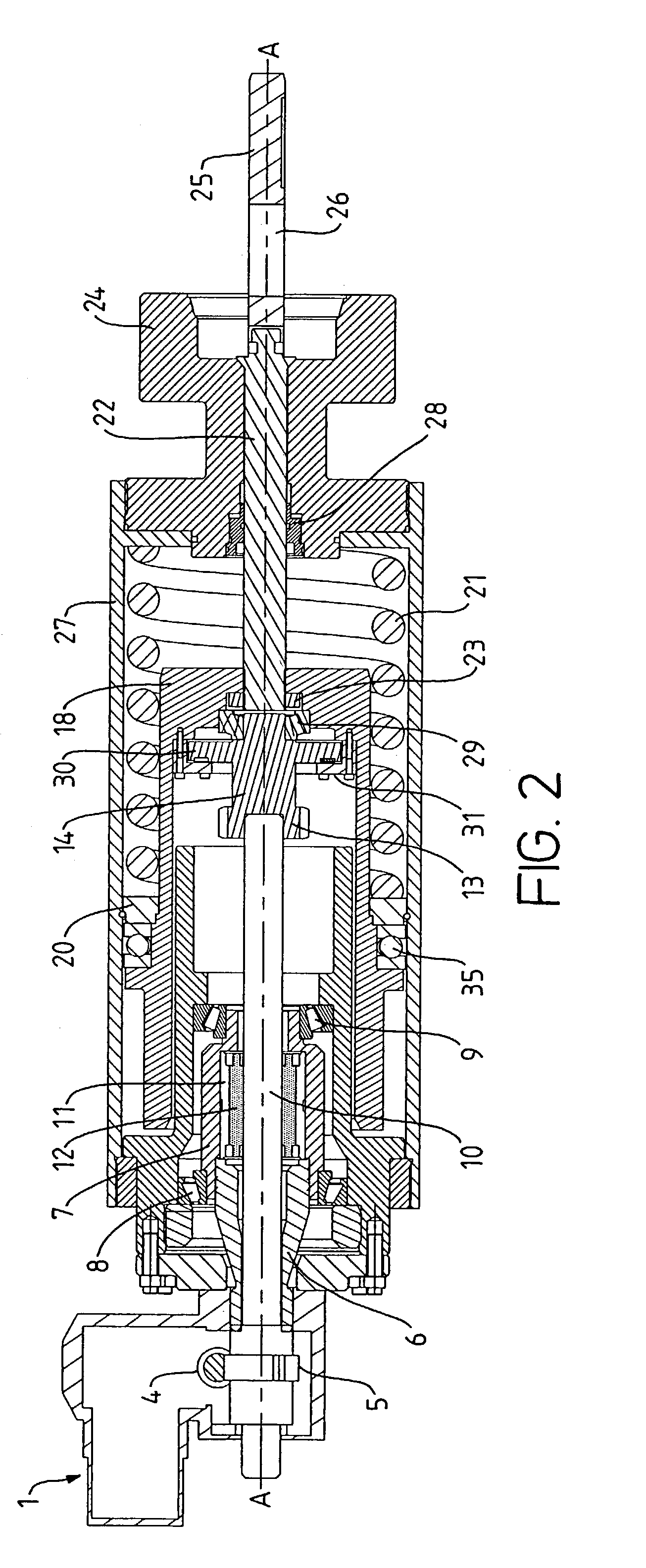
[0025]Referring to FIGS. 1–3, an electric motor unit 1 includes an electric motor 2 which drives via a shaft 3 a worm and wheel transmission in the unit comprising a worm 4 and a wheel 5. The wheel 5 is fastened to a rotatable member 6 to give a rotary output about an axis A to the member 6. The member 6 is attached to tubular roller screw mounting structure 7 such that structure 7 also rotates with member 6, structure 7 being supported by tapered-roller bearings 8 and 9. Reference numeral 10 designates an externally threaded shaft, there being an internally threaded tubular nut 11 coupled to shaft 10 as described below, tubular nut 10 being located between member 6 and the right-hand end in the figures of structure 7 and attached to the latter. Thus, tubular nut 11 rotates with member 6.

[0026]The thread on shaft 10 is coupled with the thread of the tubular nut 11. The arrangement is not a simple nut on threaded shaft, but a low friction planetary roller screw arrangement, there bei...


PUM


Abstract

A linear actuator comprises rotary motion producing means (1,2,3,4,5); linear motion producing means (6,7,10,11,12) coupled with the rotary motion producing means for converting rotary motion to linear motion; a driven member (18) movable linearly by the linear motion providing means from a first position to a second position; and backdrive means (22) for returning the driven member to the first position. The arrangement is such that the linear motion producing means includes torque reaction means (13,15,16,17) which, in normal operation, is in an activated condition and provides a torque reaction path to enable the driven member to be moved from the first to the second position but which, in the event of a fault, is in a de-activated condition so that it no longer provides the torque reaction path and the back-drive means can move the driven member to the first position, without disengaging the rotary motion producing means from the linear motion producing means.

Description

FIELD OF THE INVENTION[0001]The present invention relates to linear actuators.BACKGROUND OF THE INVENTION[0002]Linear electric actuators, i.e. electric actuators with push-pull outputs, are becoming employed in fluid extraction installations as a replacement for the traditional hydraulic linear actuators, typically employed to operate valves. One of the features of such an actuator, particularly for a subsea installation, is that the device operated by the actuator should return to a required position in the event of a failure, such as a loss of electrical control or a mechanical failure. For example, if the actuator operates a valve, then the valve must revert to a closed position, or, more rarely, to an open position, in the event of a failure. There are many actuators available on the market most of which employ an electric motor which drives, via a gearbox, a rotary to linear mechanism such as a screw drive and a small percentage of them have a fail-safe mechanism built in. Thos...

Claims


Application Information

Patent Timeline
Patent Type & Authority Patents(United States)
IPC IPC(8): F16H25/20F16K31/04
CPCF16K31/047F16H25/205Y10T74/186Y10T74/18696
Inventor DONALD, ALISTAIR ROSSDURSLEY, PAUL JOHN
Owner BAKER HUGHES ENERGY TECH UK LTD
Why Eureka
Try Eureka